Hi,
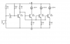
I have a question related to the circuit in the attachment down below. This is a circuit where LED's glows in music rhythm received from smartphone speaker (or any other source) that fall on electric mic. When there is no sound signal (or any other vibration near mic), Q1 transistor is on, and other transistors are off because there is not enough voltage to the bases of other transistors. With my pocket oscilloscope, I noticed that when there is a sound wave to the mic, voltage between base and emitter of Q1 is pulled down, thus transistor Q1 is opened (no current from collector to emitter) and other transistors are conducting, so LED's glows. My question is: Why is this so? Why is base pulled low when there is sound wave?
I have a question related to the circuit in the attachment down below. This is a circuit where LED's glows in music rhythm received from smartphone speaker (or any other source) that fall on electric mic. When there is no sound signal (or any other vibration near mic), Q1 transistor is on, and other transistors are off because there is not enough voltage to the bases of other transistors. With my pocket oscilloscope, I noticed that when there is a sound wave to the mic, voltage between base and emitter of Q1 is pulled down, thus transistor Q1 is opened (no current from collector to emitter) and other transistors are conducting, so LED's glows. My question is: Why is this so? Why is base pulled low when there is sound wave?