Continue to Site

Welcome to our site!

Electro Tech is an online community (with over 170,000 members) who enjoy talking about and building electronic circuits, projects and gadgets. To participate you need to register. Registration is free. Click here to register now.

  • Welcome to our site! Electro Tech is an online community (with over 170,000 members) who enjoy talking about and building electronic circuits, projects and gadgets. To participate you need to register. Registration is free. Click here to register now.

Transistor and thermistor problem

Status
Not open for further replies.

Saharkka

New Member
Hello, I'm a noob at electronics so hopefully you guys can help me out;

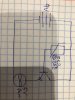
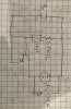
I'm trying to make a circuit that uses a transistor as a switch to a fan, the idea is to have a thermistor connected to the base of the transistor while the collector and the emitter to turn on a 5V fan when the thermistor gets to a certain temperature . Sounds fairly simple, I have attached the schematic.

However I may have misunderstood how transistors work or something, but if I understood correctly; if there is no current flowing through the base, there shouldn't be current flowing through the collector and the emitter, is this correct?

This is what happens:

The fan is on no matter what, I have tried adding resistances before to increase the temperature needed to turn the fan on, it did not work.
Then I tried disconnecting the base from the power source and the fan was still working.

So did I misunderstood how transistors works or maybe a component broke?
This is a list of what I'm using:
9V battery
5V Fan
2 P2222 transistor
10kohms thermistor

Thanks in advance!
 

Attachments

  • WhatsApp Image 2020-01-24 at 10.34.23 PM.jpeg
    WhatsApp Image 2020-01-24 at 10.34.23 PM.jpeg
    110.7 KB · Views: 257
What is the current rating of the fan? It might draw so much current that it destroyed the transistor.

Separate from that, the circuit does not have enough parts. At a minimum there needs to be a resistor from the base to GND (ground, the battery negative terminal in your case. Without this resistor, the thermistor always will pas enough current to keep the transistor at least partly turned on.

What is the thermistor part number? Or, what is its resistance at room temperature (25C)?

ak
 
Your circuit isn't turning the fan fully on and fully off. It will always provide some power to the fan. The transistor will get hot, because there will be current thought it and a voltage across it at the same time. The transistor is rated at 625 mW (https://www.onsemi.com/pub/Collateral/P2N2222A-D.PDF) so when there is 4 V across it, anything over 150 mA will overheat it. You don't say how big the fan is, or how big the battery is, but 5 V fans that only take 150 mA are quite small and they may take more current when starting up.

What you need is a suitable power supply for the fan, at the correct voltage. That might be a 9 V battery and a regulator. A PP3 battery won't run a 150 mA fan for long. That current is really too much for a PP3, but there are larger batteries.

A linear regulator will get hot, and a switch-mode regulator will be more complicated.

To turn the fan on and off, you need some sort of amplifier, maybe a couple of transistors, that switches fully on and fully off, so that it doesn't run in a partially on mode where it gets hot. You can switch the 9 V going into the regulator, or the 5 V coming out of the regulator. Some regulators have a low-power input that allows then to be turned off and on.

You could just use a power bank which will be fine at up to 1 A. Some will turn off if you don't take current from them, when the fan stops, and need turning on with a button.
 
Welcome to ETO!
Fans (and other things having wire coils) have a property called 'inductance' which can cause large voltage spikes to be generated when they switch off. These spikes need to be suppressed or the transistor can be fried (which has perhaps happened to your transistor if it won't turn off). A reverse-biased diode connected across the fan is commonly used as a suppressor.
 
The schematic assumes a 10k thermistor at 20°C.
The 2400 ohm resistor can be replaced with a 5k pot wired as a rheostat.

53782E9B-C4B1-4EF3-BBC3-298A43C7286E.jpeg
 
Hello, sorry for the late response, I have been very busy and thanks for the feedback!

I'll be answering with further details, today I'm going to buy a few things to try and re-do this circuit, hopefully it will work this time around.

AnalogKid: the rating of the fan is 0.25A. This time around I will connect the base to the negative side to test it out. The thermistor has a 10kOhm rating at 25ºC.

Diver300: Then I guess I will have some trouble because the fan has to run at 5V at 0.25A, so even if I limit the voltage it will still burn the transistor, so maybe I have to use another transistor.

alec_t : thanks for the suggestion, that might prevent me from going from too many transistors before making it work lol.

gophert : Thanks for the schematic! I will try to figure it out on my own, mainly to learn. If not I will use yours as base. I do have a question, why are you using a transistor array in the circuit?
 
Last edited:
@gophert : Thanks for the schematic! I will try to figure it out on my own, mainly to learn. If not I will use yours as base. I do have a question, why are you using a transistor array in the circuit?

The two transistors are connected to multiply the gain (it is called a Darlington - after the inventor). The very high gain of a Darlington arrangement allows your thermistor to "more" effectively turn on-off the LEDs instead of a slower fade. I was trying to limit the design to parts that you mentioned so you didn't have to buy more parts.

If you are in the mood to buy more parts, you should consider a "comparator". Also look up "hysteresis" so your design doesn't flicker as the temperature passes through the on/off transition.
 
If the transistor is used properly as a switch with the fan and diode connected between the +5V and the collector of the transistor then the turned-on transistor
has a voltage across it of only 0.2V and with the 250mA of current, the transistor heats with only 0.2V x 250mA= 0.05W which is nothing. It is the fan that heats with 4.8V x 250mA= 1.2W.
 
When using a fan like a basic home computer 12 VDC fan and only wanting to turn it On/Off based on a temperature and using a thermistor as a temperature sensor. You want to turn your transistor fully on which we call saturation or you want your transistor fully off. You do not want your transistor in what can be called the linear region.

A simple Google of "2N2222 thermistor fan circuit" will get you a collection of circuits. Using your 2N2222 NPN transistor you will find most better circuits include the use of a simple operational amplifier or comparator, I like comparator circuits better but even an ancient LM741 op-amp will work. The idea is the comparator or op-amp allows you to set a temperature where the output changes state and that state change turns your transistor on or off which in turn drives your fan on or off. You may want to consider some of the circuits I linked to.

Ron
 
Hello guys,

I did some modifications, now I have the reverse problem , now the fan won't turn on lol.
However I have not tested other alternatives yet. I'll leave the schematic that I have tried below (sorry for the ugliness of it, I was in a bit of a hurry), I will try putting the fan in front of the emitter and other "what ifs" to see if something works.

A couple of you have suggested using a comparator and thanks for the suggestion, but I'm doing this mainly as a learning excerciese so first I want to successfully doing something with a simple transistor (other than turning a LED on), probably there are better projects for that and suggestions are welcome. But also I want to study how a comparator works so hopefully if I don't make this work now, later I can come back to this application and try again with more knowledge.

Reloadron I Will defenetely look into the use of opamps and comparators, I do not know how they work or how yet, so I might take a bit.

Thanks for your help and suggestions!
 

Attachments

  • 1581192729132.png
    1581192729132.png
    627.5 KB · Views: 236
Last edited:
You shorted the base and emitter of the transistor so it will never turn on.
also, you show a circle with + and - that is not your load.
 
You shorted the base and emitter of the transistor so it will never turn on.
also, you show a circle with + and - that is not your load.

gophert : Thanks for the schematic! I will try to figure it out on my own, mainly to learn. If not I will use yours as base. I do have a question, why are you using a transistor array in the circuit?

I suggest you stop figuring it out that way. Transistors have a right way to be employed. Just build what gophert provided and learnt from there. Otherwise you are wasting everybody's time, yours included.
 
I gave yopu a link and a few suggestions. Apparently you would rather just hope you connect something right and it works. You now have your base of the transistor tied to ground so it will never turn on. Get a clue how things work.

Ron
 
Status
Not open for further replies.

New Articles From Microcontroller Tips

Back
Top