Continue to Site

Welcome to our site!

Electro Tech is an online community (with over 170,000 members) who enjoy talking about and building electronic circuits, projects and gadgets. To participate you need to register. Registration is free. Click here to register now.

  • Welcome to our site! Electro Tech is an online community (with over 170,000 members) who enjoy talking about and building electronic circuits, projects and gadgets. To participate you need to register. Registration is free. Click here to register now.

Transistor AMPLifier HelP !!!!

Status
Not open for further replies.

sudar_dhoni

New Member
1) i cant understand the basics
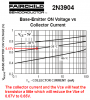
i want to know what do u mean by voltage between emitter and base and voltage between collector and base
is it the barrier voltage ???
i.e the barrier potential at the juctions EB an CB???
the depletion region is responsible for the voltage drop in diode
in forward bias also there exists voltage drop according to my book
but in forward bias the depletion region would have vanished,then how will there be voltage drop.


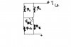
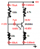
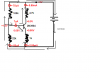
2)also i cant understand voltage divider bias
i have posted the circuit diagram
i have many doubts there about how the voltage drop between R1 and R2 gives forward bias to the base emitter
also which current's voltage is getting dropped there
in my diagram its showing collector current
but collector current itself arises from the emitter
also u have not biased the emitter till now then how did u get Ic

forward bias provided by the voltage drop of Ic
see u have not biased it and u r about to bias the emitter only from voltage drop of Ic
then where did u get that Ic from
Ic comes only after biasing EB

plz BOB S answer first question 1 and then 2
if u cant understand my question plz mention it i will try to ask it in a better way
 

Attachments

  • voltage divider bias.JPG
    voltage divider bias.JPG
    23.2 KB · Views: 446
I calculated some resistors for your transistor circuit. I used a 9V supply.

1) The voltage divider tries to supply +1.62V to the base of the transistor but the 7uA of base current reduces the divider's voltage to +1.5V.
2) The datasheet of the transistor shows that its base-emitter voltage is 0.65V when the collector current is 0.85mA.
3) 1.5V - 0.65V= 0.85V which is the emitter voltage.
4) The collector current is almost the same as the emitter current which is 0.85V/1k= 0.85mA.
5) The collector resistor has a voltage drop of 0.85mA x 4.7k= 4.0V then the collector voltage is 9V - 4V= +5V.
 

Attachments

  • biased transistor3.PNG
    biased transistor3.PNG
    19.8 KB · Views: 327
I calculated some resistors for your transistor circuit. I used a 9V supply.

1) The voltage divider tries to supply +1.62V to the base of the transistor but the 7uA of base current reduces the divider's voltage to +1.5V.
2) The datasheet of the transistor shows that its base-emitter voltage is 0.65V when the collector current is 0.85mA.
3) 1.5V - 0.65V= 0.85V which is the emitter voltage.
4) The collector current is almost the same as the emitter current which is 0.85V/1k= 0.85mA.
5) The collector resistor has a voltage drop of 0.85mA x 4.7k= 4.0V then the collector voltage is 9V - 4V= +5V.

super explanation ur a genius who can understand my feelings very well
still i some more doubts here that i have mentioned below
1) could u explain it entire circuit in terms of electron movement i.e how the voltage drops in each component in terms of electron flow

2)1) The voltage divider tries to supply +1.62V to the base of the transistor but the 7uA of base current reduces the divider's voltage to +1.5V.

u r telling that the voltage 9v gets dropped to 1.62 after crossing 100k and that the base current 7ua is dropping it further to 1.5v how does this happen also
till now u have not biased the emitter base then where did u get that base current(also the base current u r referring to is it electron movement of conventional?)
 
1) could u explain it entire circuit in terms of electron movement i.e how the voltage drops in each component in terms of electron flow

Use ohm's Law to calculate the currents and the voltage drops.

u r telling that the voltage 9v gets dropped to 1.62 after crossing 100k and that the base current 7ua is dropping it further to 1.5v how does this happen?
The 7uA of base current adds 7uA to the 100k resistor so its voltage drop increases to 7.5V.

till now u have not biased the emitter base then where did u get that base current(also the base current u r referring to is it electron movement of conventional?)
The base-emitter junction is a forward-biased diode with a voltage of 0.65V and it conducts current as shown in the datasheet.
 
are u explaining the ciruit in terms of electron movement or conventional?
could u plz mark how the electrons flow in the circuit diagram that u have posted


[/B]

The 7uA of base current adds 7uA to the 100k resistor so its voltage drop increases to 7.5V.

i cant understand what u mean by this
u have shown 75uA comes to 100K with a energy or voltage of 9v
it itself drops 7.5 volts and has 1.5 volts how did that 1.62v come from also from where did that .65v which forward biases the EB come from come from


[/B]
The base-emitter junction is a forward-biased diode with a voltage of 0.65V and it conducts current as shown in the datasheet.

but u have marked .85 volts for the emitter
i can understand better if u show the directions of electron flow because i want to know only about reality and not conventional
 
are u explaining the ciruit in terms of electron movement or conventional?
could u plz mark how the electrons flow in the circuit diagram that u have posted
It does not matter which way the electrons flow. The base of the transistor has 7uA of current and the collector and emitter have 0.85mA of current.

i cant understand what u mean by this
u have shown 75uA comes to 100K with a energy or voltage of 9v
it itself drops 7.5 volts and has 1.5 volts how did that 1.62v come from also from where did that .65v which forward biases the EB come from come from
If the base current is not there then the 100k and 22k voltage divider produce a current of 73.8uA and a voltage of +1.62V. The 7uA of base current adds a little to the 100k and is subtracted a little from the 22k resulting in +1.5V at the base of the transistor.

The datasheet for every transistor shows its base-emitter voltage at various collector currents. It is 0.65V for the 2N3904 transistor when its collector current is 0.85mA.

but u have marked .85 volts for the emitter
The 1.5V at the base minus the Vbe of 0.65 equals +0.85V at the emitter.

i can understand better if u show the directions of electron flow
because i want to know only about reality and not conventional
The direction of the current does not matter. The transistor base needs current and it amplifies the current producing a higher current at the collector.
 

Attachments

  • biased transistor4.PNG
    biased transistor4.PNG
    21.1 KB · Views: 400
It does not matter which way the electrons flow. The base of the transistor has 7uA of current and the collector and emitter have 0.85mA of current.


If the base current is not there then the 100k and 22k voltage divider produce a current of 73.8uA and a voltage of +1.62V. The 7uA of base current adds a little to the 100k and is subtracted a little from the 22k resulting in +1.5V at the base of the transistor.

The datasheet for every transistor shows its base-emitter voltage at various collector currents. It is 0.65V for the 2N3904 transistor when its collector current is 0.85mA.


The 1.5V at the base minus the Vbe of 0.65 equals +0.85V at the emitter.


The direction of the current does not matter. The transistor base needs current and it amplifies the current producing a higher current at the collector.

1)i cant understand the voltage divider bias i find it extremely difficult
plz explain it interms of electron movement
2)also to be frank i cant understand what basically Vbe and Vce is
is it the barrier voltage between base emitter and base collector respectively
if so then how can voltage drop occur at CB junction
it experiences no impedance and only attraction then how can the voltage drop there
3)also very imp one
how can there be a barrier voltage of .7 in pn junctions when it is forward biased.As soon as it is forward biased the depletion region vanishes.Then how can there be a barrier voltage.

i have provided the circuit diagram
plz answer 1 by 1
 
The depleation region does not dissappear as soon as forward bias is applied. It is always present, but it is modified.

Vbe and Vbc are determined by the bias arrangement AND the transistor characterists, and are easily calculated as AG's posts clearly show.

If you can't understand a simple voltage divider, then you should do a very thorough review of basic DC circuitry. It's simple Ohm's law for calculation of voltages, ressitances and currents. Look at it this way: the current through any series connected resistros is the applied voltage divided by the total resistance of the series:

I = V(applied)/R(total) - Ohm's law

Knowing the current, and understand that current is constant in any series cirsuit, you can calculate the voltage across any one of the series connected resistors.

V(any single resistor) = I*R

or, using the first eqn in the second:

V(any single resistro) = R*V(applied)/R(total)

thus:

V(any single resistor) = V * R/R(total)
 
1)i cant understand the voltage divider bias i find it extremely difficult
use Ohm's Law:
a) the resistors are a 100k and a 22k for a total of 122k.
b) 9V/122k is a current of 73.8uA.
c) 73.8uA in the 22k resistor produces 1.62V.
d) For the base voltage to be +1.5V then the 100k resistor has (9V - 1.5V)/100k= 75uA in it. the base of the transistor takes 7uA and the 22k resistor takes 68uA.

plz explain it interms of electron movement
Electron movement has nothing to do with it. Just calculate the voltages and currents using Ohm's Law and simple arithmatic.

2)also to be frank i cant understand what basically Vbe and Vce is
is it the barrier voltage between base emitter and base collector respectively
if so then how can voltage drop occur at CB junction
it experiences no impedance and only attraction then how can the voltage drop there
The base-emitter is a forward-biased diode. The transistor amplifies base current to produce a much higher collector to emitter current.
Forget about the collector-base junction because it is reverse-biased most of the time and does not conduct.

3)also very imp one
how can there be a barrier voltage of .7 in pn junctions when it is forward biased. As soon as it is forward biased the depletion region vanishes.Then how can there be a barrier voltage.
A forward-biased silicon diode has a voltage of about 0.7V. You do not need to know why.
 
It gets into alot of device physics, modified energy levels and so forth. The region also narrows, but never completely disappears. There is always a barrier voltage present.
 
use Ohm's Law:
a) the resistors are a 100k and a 22k for a total of 122k.
b) 9V/122k is a current of 73.8uA.
c) 73.8uA in the 22k resistor produces 1.62V.
d) For the base voltage to be +1.5V then the 100k resistor has (9V - 1.5V)/100k= 75uA in it. the base of the transistor takes 7uA and the 22k resistor takes 68uA.

u have only mentioned these values
see for R1 current flowing is 75uA
for R2 u have mentioned 68uA
then u r saying series
series means same current must flow but u have shown different currents
 

Attachments

  • biased transistor5.PNG
    biased transistor5.PNG
    28 KB · Views: 202
Last edited:
how did u add up the resistors just like that
they are in parallel
You are completely wrong and do not know the basics of electronics.
The base bias resistors are in series so their resistances simply add.

the reason behind me insisting on electron flow is that
all that u have calculated holds true for conventional current
if u consider electron flow
the same values wont come
Current is current. The direction of the current does not change the numbers.

In my figure i myself have marked the electron movement plz say whether it is right
if so some electrons are going to the base
but actually in a npn transistor electrons go from the negative terminal to the emitter and split into base current and collector current.But in this case some electrons are also going to the base.plz solve my problem and now in case of this electron flow which causes the forward bias of the base and emitter
The direction of the current does not matter.
 

Attachments

  • series and parallel again.PNG
    series and parallel again.PNG
    19.5 KB · Views: 173
You are completely wrong and do not know the basics of electronics.
The base bias resistors are in series so their resistances simply add.


Current is current. The direction of the current does not change the numbers.


The direction of the current does not matter.

use Ohm's Law:
a) the resistors are a 100k and a 22k for a total of 122k.
b) 9V/122k is a current of 73.8uA.
c) 73.8uA in the 22k resistor produces 1.62V.
d) For the base voltage to be +1.5V then the 100k resistor has (9V - 1.5V)/100k= 75uA in it. the base of the transistor takes 7uA and the 22k resistor takes 68uA.

u have only mentioned these values
see for R1 current flowing is 75uA
for R2 u have mentioned 68uA
then u r saying series
series means same current must flow but u have shown different currents
 
for R1 current flowing is 75uA
for R2 u have mentioned 68uA
then u r saying series
series means same current must flow but u have shown different currents
Yes the resistors are in series. But the base-emitter junction of the transistor is parallel to R2.

So the 68uA in R2 plus the base current of 7uA add to make the 75uA current in R1.
 
Status
Not open for further replies.

Latest threads

New Articles From Microcontroller Tips

Back
Top