Continue to Site

Welcome to our site!

Electro Tech is an online community (with over 170,000 members) who enjoy talking about and building electronic circuits, projects and gadgets. To participate you need to register. Registration is free. Click here to register now.

  • Welcome to our site! Electro Tech is an online community (with over 170,000 members) who enjoy talking about and building electronic circuits, projects and gadgets. To participate you need to register. Registration is free. Click here to register now.

transformers and sudden current draw from them

Status
Not open for further replies.

qtommer

Member
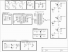
hi i have a MCU circuit board powered up as follows:

Transformer (9VA) ====>7805 Voltage Regulator====>PIC16F876A
(Board maximum current requirement=0.45A so transformer ratings are fine)

Is it possible that due to poor regulation of most common transformers, that a sudden current draw (say a relay gets activated and draws current for the coil) would result in unstability of the transformer? I say unstability because each time i turn on the relay, my PIC will reset. (My PIC MCLR is tied to Vcc via a pull up resistor).

I am using an NPN transistor switching circuit. I am quite certain its the relay drawing the sudden current that is the problem. If I disconnect the relay, (an open circuit between collector of transistor and Vcc) and I drive the transistor base (turn on the relay), the system remains stable only until I connect the relay back again and the system resets.

So once again, could it be due to the transformer problem? When I power my circuit via a power supply bench, none of the sort happens..

Hope to hear from you experts..

Thanks!:)
 
Does the MCU reset when the relay pulls-in or when the MCU turns it off?

Measure the relay coil resistance with an Ohmmeter. Say it is 100Ω. Replace the relay coil with a 100Ω 1W resistor. Does the MCU reset when switching the resistor?

Is the relay powered through the regulator or is it fed from the unregulated voltage going into the regulator (my choice)?

Pulling-in an inductive relay is less demanding than switching a resistor of equal resistance. Switching it off is a different matter.
 
Last edited:
Post your circuit, including the transformer and regulator.
 
i have attached the circuit. the relays are powered through the regulator. In the attached schematic, all nodes labelled '5V' are connected to the output of the 7805.
Once again, just to be clear, there was no problem at all when I powered the circuit from the DC bench power supply. The resistance of the coil is 63 ohms. The transistor circuit has been designed accordingly.

thanks:)

*edit: oh and the boxes at the relay circuit are actually connected to the relay coils
 

Attachments

  • circuit.png
    circuit.png
    49.9 KB · Views: 159
Last edited:
I have to ask? Why bother using opto-isolators if the relays share the same power supply as the MCU???? The benefit of using the optos is that the power supply for the inductive loads can be kept totally separate from the MCU's (and analog circuits, if any).

My choice would have been to use 12V relays (~40% of the current of 5V ones), power them with the unregulated voltage, not use the optos. I just got through building a PIC system of similar complexity to yours, and it works glitch free.


Your root problem is the 47uF capacitor between the rectifier and the input of the regulator. It needs to be > 1000uF
 
Last edited:
thanks for your reply.

im not using opto-isolators...the boxes are just for the PCB design purposes where i place turn pins there which extend out to the relay coils on another board via jumper wires :)


As you recommended 1000uF , the deduction i get is that the ripple has to be as miniscule as possible. Does this mean that the ripple magnitude (assuming a 0.5V ripple) is still bad eventhough it has the DC level well above what is required for input to the regulator?

thanks:)
 
Last edited:
No, the ripple just has to be low enough that the 7805 regulator gets its minimum voltage (7V) above its dropout voltage (2V).

Three 63 Ohm relays draw 238mA, plus some leds and the MCU, say the total is ~0.3A.

C*ΔV = i*t, where ΔV is the ripple, C is in farads, i is the load current, and t is 10ms for 50Hz.

C = i*t/ΔV = 0.3*0.01/2 = 1500uF, not a bad guess, above. This is based on a 2V ΔV, where you have 9Vdc dropping to 7V under load.
 
Last edited:
thanks for your reply.

im not using opto-isolators...the boxes are just for the PCB design purposes where i place turn pins there which extend out to the relay coils on another board via jumper wires :)


As you recommended 1000uF , the deduction i get is that the ripple has to be as miniscule as possible. Does this mean that the ripple magnitude (assuming a 0.5V ripple) is still bad eventhough it has the DC level well above what is required for input to the regulator?

thanks:)

Yes, 47uF is far too small - and as MikeMl suggests, it's better to feed the relays from before the regulator, saving a LOT of power, and further removing the relay connections from the PIC. With only a 47uF capacitor I would imagine the supply rail dips well down when the relay triggers, thus reseting the PIC.
 
thank you both so much!..im really learning alot..(practical and theory wise) thanks Mike for the calculations..i understand the 10ms is due to the doubling of the frequency after centre tapped rectification..
can't wait to try out the suggested methods tomorrow!:D

thanks again!
 
Status
Not open for further replies.

Latest threads

New Articles From Microcontroller Tips

Back
Top