I've got a small mains transformer with a single primary winding for 120Vac. It was taken from a cheap 20W stereo system.
The secondary side has 4 wires: 2 brown, 2 yellow, all the same gauge.
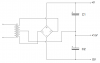
I hooked the transformer to the wall and there are 22V brown1 to brown2, and 22V yellow1 to yellow2. This seems like a dual-secondary winding configuration.
However, when I measure between brown1-yellow1, brown2-yellow2, brown1-yellow2, and brown2-yellow1, there are certain other voltages (dont quite remember, they were odd... 15ish and 6ish I think). This makes me think that it is a single secondary winding with 4 taps.
The way it appeared to be used was yellow1/2 for one power circuit regulated to 12V and brown1/2 for a separate power circuit regulated to 5V.
not sure which is more likely. I would like to use both in a similar manner (one low-power side for indicators and such, and the high-power side for amplification)
The secondary side has 4 wires: 2 brown, 2 yellow, all the same gauge.
I hooked the transformer to the wall and there are 22V brown1 to brown2, and 22V yellow1 to yellow2. This seems like a dual-secondary winding configuration.
However, when I measure between brown1-yellow1, brown2-yellow2, brown1-yellow2, and brown2-yellow1, there are certain other voltages (dont quite remember, they were odd... 15ish and 6ish I think). This makes me think that it is a single secondary winding with 4 taps.
The way it appeared to be used was yellow1/2 for one power circuit regulated to 12V and brown1/2 for a separate power circuit regulated to 5V.
not sure which is more likely. I would like to use both in a similar manner (one low-power side for indicators and such, and the high-power side for amplification)

")