Continue to Site

Welcome to our site!

Electro Tech is an online community (with over 170,000 members) who enjoy talking about and building electronic circuits, projects and gadgets. To participate you need to register. Registration is free. Click here to register now.

  • Welcome to our site! Electro Tech is an online community (with over 170,000 members) who enjoy talking about and building electronic circuits, projects and gadgets. To participate you need to register. Registration is free. Click here to register now.

Transformer kickback

Status
Not open for further replies.

illconductor

New Member
hi. my question involves a 240 to 12v transformer. since im using it to step up voltange now ill refer to the 12v side as primary. if you touch 12v to the primary you dont just get 240v but something alot higher maybe 3kv as a spart can jump from the secondary termals about 3mm. im wondering why this is, and why i have never seen it listed as a problem on peoples inverter disscussion. if i feed a square wave into the primary- instead of 240v out, wont i get 3kv out?
 
That happens because a square has a high dV/dt. Voltage across an inductor is proportional to dV/dT. You can either use a sine wave, try a diode across the primary to tame the voltage or just call it your high voltage supply.

Glad you weren't hurt.

PS: is it a killivolt/mm or killivolt/cm???
 
Last edited:
aha, can you tell me what dV/dt is? a very quick change in voltage? ( have a formula?)

and i also noticed that the spark i get when i connect the primary to battery is larger than if i short the battery leads themselves. so there must be some effect happening there too. any ideas?

thanks
 
Yes, large change in voltage. Can you tell me how you're driving the transformer's secondary? Can you post a drawing. I have a hunch that you're using a transistor and turning it on and off. That will create a VERY large spike. NO, I don't have any equations. It all depends on how fast your driving element ( transistor? ) turns off.
 
yeah transistor switching see diagram below, and both the transistors go to a centretap now.

its wierd when i use straight battery on the transformer it produces 3mm long sparks, but using the transistors, no sparks. i think it has to do with the amount of current the transitors can supply. or maybe hysteresis in the transformer is smoothing out the output voltage from the secondary?
 
there you go
 

Attachments

  • DSCF0156.JPG
    DSCF0156.JPG
    1,020.8 KB · Views: 214
What you've built is a "flyback" circuit. When you driving transistor is on, current quickly builds in the transformer primary. When it it suddenly switched off, the field around the primary coil suddenly collapses, and huge voltage spikes results. This can fry all your electronics and power supply if you don't do something about it ( now, ask me why I know that :) ) You might try a snubber across your coil's primary to provide a path to slowly discharge the overcurrent. At a minimum, it can include a reversed biased doide connected across the primary terminals.
 
That happens because a square has a high dV/dt. Voltage across an inductor is proportional to dV/dT. You can either use a sine wave, try a diode across the primary to tame the voltage or just call it your high voltage supply.

Glad you weren't hurt.

PS: is it a killivolt/mm or killivolt/cm???
Actually, V is proportional to di/dt, the rate of change in the current. The proportionality factor is the inductance.
The high voltage spike actually occurs when you remove the 12V supply from the primary, as BrownOut has stated.
 
Last edited:
hmm thanks guys.

well so that explaines the first phenomenon.. hv from the secondary when you apply and quickly remove current to the primary. so you need to make it sine wave input to just get the turns ratio votage.

and the hv generated in the primary, use a diode to handle it.

yeah back EMF, i think that is one of my problems. im using d cell batteries to go through tip122 which can switch 8 amps. this goes into a 150ma 12,12 ctap transformer. now im trying to make an inverter, i havent measureed the current from the secondary but im pretty sure its bugger all.. i assume the back EMF is stopping sufficient current from flowing through the primary. that is i doubt the full 8 amps is flowing. so i figured that ill just need a higher voltage to increase the current flow, but then ill get a higher voltage out of the secondary which i dont want, and ill hit the maximum voltage for the transitors too ( im already using 12v). so what do you do to get good current output from the secondary? ive looked at other peoples shematics and they basically are doing what im doing. 12 into a 12v 240v transformer
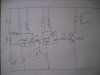
 
I think you're getting off-track. You only want enough current to flow to give you the 240V ( or whatever ) you need. Flowing more current will solve no problem, but will give you more output voltage. You control current by the transistor's "ON" time. The longer the transistor is left on, the more current flowing, and visa-versa. Using a diode in the primary will help to keep down the secondary voltage as well.
 
hmm i appriciate your answer but im not sure its right.

more current wont equal more voltage. that is once the transformer is charged. flowing more current will flow more current at 240 at the secondary- which is what i want since im making an inverter.
 
yeah cheers.

i have a similar circuit , but im having trouble getting good current flow through the transistors and transformer. im using 2 x tip122 and a 150ma 12 , 12 :240 centretap transformer. does anyone know what the problem would be. for instance i hooked up the transistors to an 8 ohn 8 watt speaker and it didnt blow it up.
 
First, how are you expecting 8A in a 150mA transformer?

i havent measureed the current from the secondary but im pretty sure its bugger all.
I look up 'bugger', and it has nothing to do with electronics. Perhaps your transformer has been abused?
 
Last edited:
Status
Not open for further replies.

Latest threads

New Articles From Microcontroller Tips

Back
Top