Continue to Site

Welcome to our site!

Electro Tech is an online community (with over 170,000 members) who enjoy talking about and building electronic circuits, projects and gadgets. To participate you need to register. Registration is free. Click here to register now.

  • Welcome to our site! Electro Tech is an online community (with over 170,000 members) who enjoy talking about and building electronic circuits, projects and gadgets. To participate you need to register. Registration is free. Click here to register now.

Transfering DATA between two pics via SPI OSHONSOFT

Status
Not open for further replies.
By "package" I mean that you can get the PIC18F4620 in a 28 pin dip (soic), a 40 pin dip (soic) or a 44 pin TQFN.
That means that some pins are not there in the different packages (i.e. a 28 pin dip won't have as many pins as a 44 pin TQFN).
So, functionality gets moved around, depending on the package.

From what I'm seeing, the PIC18LF4431 is a 3.3v device and the PIC18F4620 is a 5v device.
Could there be some kind of level shifting needed?
Hi M,
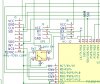
Ah yes! They are both 44PIN TQFN and both are running at 3.3V.
C.
 
camerart: I'm so glad I took the time to read your latest post.

I would have looked silly belaboring the point. :D

I would shut off -all- on-board peripherals on the master, You might be getting an interrupt in the middle of the SPI transaction which might be polluting the data.
 
camerart: I'm so glad I took the time to read your latest post.

I would have looked silly belaboring the point. :D

I would shut off -all- on-board peripherals on the master, You might be getting an interrupt in the middle of the SPI transaction which might be polluting the data.
Hi M,
Same result since now only two PICs, nothin else, apart from HSEROUT on each PIC for testing.
C.
 
Hi M,
Same result since now only two PICs, nothin else, apart from HSEROUT on each PIC for testing.
C.
Are you using Oshonsoft Basic functions SpiSend, SpiReceive in the master?
You could make a simple test to check the communication between master and slave.
In the slave disable interrupts, setup the slave and make a loop that blinks a led.
Check the pins and their directions, master SDO is output and goes to slave SDI input, master clock is output and goes to slave clock input... etc.
The master program:
Code:
SPICSOn
for a=1 to 10
  SPISend a
  SPIReceive b
  Hserout #b
next a
You should get 1,2...,10 in the terminal.
 
Last edited:
Are you using Oshonsoft Basic functions SpiSend, SpiReceive in the master?
You could make a simple test to check the communication between master and slave.
In the slave disable interrupts, setup the slave and make a loop that blinks a led.
Check the pins and their directions, master SDO is output and goes to slave SDI input, master clock is output and goes to slave clock input... etc.
The master program:
Code:
SPICSOn
for a=1 to 10
  SPISend a
  SPIReceive b
  Hserout #b
next a
You should get 1,2...,10 in the terminal.
Hi J,
EDIT: Yes Oshonsoft
There seems to be a problem with SCK.
I tried a simple test: Toggle SCK, SDO, SDI, and only SDO showed toggling.
Bearing in mind that the SLAVE is set to accept SCK and SDO, this shows a problem with SCK.
Yesterday I disconnected the connections and all 4x toggled.

Here is the SLAVE program:

The SSPBUF, Y, and AZIMUTH all show counting, when I use the test buttons.

C.
 

Attachments

  • 18F4431 8MHz INT COUNT 0_359 SPI 030219 1600.bas
    2.4 KB · Views: 188
Last edited:
Hi J,
EDIT: Yes Oshonsoft
There seems to be a problem with SCK.
I tried a simple test: Toggle SCK, SDO, SDI, and only SDO showed toggling.
Bearing in mind that the SLAVE is set to accept SCK and SDO, this shows a problem with SCK.
Yesterday I disconnected the connections and all 4x toggled.

Here is the SLAVE program:

The SSPBUF, Y, and AZIMUTH all show counting, when I use the test buttons.

C.
These are for Oshonsoft master!
Define SPI_CS_REG = PORTC '[used when in slave mode]
Define SPI_CS_BIT = 6 '[used when in slave mode]
Define SPI_SCK_REG = PORTD
Define SPI_SCK_BIT = 3
Define SPI_SDI_REG = PORTD
Define SPI_SDI_BIT = 2
Define SPI_SDO_REG = PORTD
Define SPI_SDO_BIT = 1
WaitMs 100
SPIPrepare
You should setup the HW Slave.

If there are clock problems, check the pin directions.
The slave clock is input only.
Hi J,
A bit confusing!

The program I posted #25 is for the SLAVE (18F4431)

I have the MASTER SPI (18F4620) set like this:
'SPI
''''''''Define SPI_CS_REG = PORTD [USED WHEN IN SLAVE MODE] NOT USED
''''''''Define SPI_CS_BIT = 4[USED WHEN IN SLAVE MODE] NOT USED
Define SPI_SCK_REG = PORTC
Define SPI_SCK_BIT = 3
Define SPI_SDI_REG = PORTC
Define SPI_SDI_BIT = 4
Define SPI_SDO_REG = PORTC
Define SPI_SDO_BIT = 5
SPIPrepare

Is this incorrect?

The PICs are wired as HW MASTER SLAVE
C.
 
Last edited:
Hi J,
A bit confusing!

The program I posted #25 is for the SLAVE (18F4431)

I have the MASTER SPI (18F4620) set like this:
'SPI
''''''''Define SPI_CS_REG = PORTD [USED WHEN IN SLAVE MODE] NOT USED
''''''''Define SPI_CS_BIT = 4[USED WHEN IN SLAVE MODE] NOT USED
Define SPI_SCK_REG = PORTC
Define SPI_SCK_BIT = 3
Define SPI_SDI_REG = PORTC
Define SPI_SDI_BIT = 4
Define SPI_SDO_REG = PORTC
Define SPI_SDO_BIT = 5
SPIPrepare

Is this incorrect?

The PICs are wired as HW MASTER SLAVE
C.
It is correct for the master but incorrect for the slave.
For the pic18f4431 set SPICON and SSPSTAT as SPI slave.
Set the iopins correctly (trisc directions)
 
This is the problem with using libraries. I don't even know if it's software or hardware. Just work through the data sheet and setup the SPI module yourself. It's not that hard and works every time.

Mike.
 
It is correct for the master but incorrect for the slave.
For the pic18f4431 set SPICON and SSPSTAT as SPI slave.
Set the iopins correctly (trisc directions)
Hi J,
I'm pretty sure I have the correct MASTER SLAVE, including the TRIS IN and OUT settings.
I'm also pretty sure I have the PINs between the two PICs connected correctly.

With all of the tests so far, only the SCK shows and error in a digital analyser of not switching.
C.
 
This is the problem with using libraries. I don't even know if it's software or hardware. Just work through the data sheet and setup the SPI module yourself. It's not that hard and works every time.

Mike.
Hi M,
For you it's not difficult, think yourself lucky. For me it's not easy, I've been trying for weeks.
C
 
The point I was making was that you are trying to use the libraries. If you learn to use the chip instead then it will always work no matter what language you write in.

Mike.
 
The point I was making was that you are trying to use the libraries. If you learn to use the chip instead then it will always work no matter what language you write in.

Mike.
Hi M,
I don't know what you mean by libraries. I have been using the D/S to find the settings in my programs, but I find it too complicated.
C.
 
Hi,
I may have found a way round my problem!

On the MASTER PCB, there is a switch. This is because the RX can only accept 1x INPUT. The switch allows 2x INPUTS

I've found a 4x way switch MAX4734, which if it works will allow 3x INPUTs, including the SLAVE HSEROUT, instead of SPI.

Will this switch work?
C.
 

Attachments

  • Switch.jpg
    Switch.jpg
    87.5 KB · Views: 222
  • MAX4734 MSOP.png
    MAX4734 MSOP.png
    5.7 KB · Views: 235
Hi J,
I'm pretty sure I have the correct MASTER SLAVE, including the TRIS IN and OUT settings.
I'm also pretty sure I have the PINs between the two PICs connected correctly.

With all of the tests so far, only the SCK shows and error in a digital analyser of not switching.
C.
Once again: don't use the Define SPI things in the Slave program.
At least the Define SPIClock conflicts with the Master clock.
It makes the slave clock pin as output.
Can you remove all these defines and use trisc instead.
Disable the interrupts and remove the QEI code and make the simple test in msg#24
Hi J,
SLAVE
Do you mean TRISD not TRISC? (SLAVE 18F4431) I've wired to the normal PINs not the alternative ones.
C.
 
Last edited:
Hi J,
Here's the terminal readout, this keeps repeating.
C
 

Attachments

  • TEST.jpg
    TEST.jpg
    22.7 KB · Views: 216
Hi ,
As I said back in #8, I'm going to have to concede defeat, it's just too difficult.

If the idea about the switch #34 doesn't work, I'll have to re-try and come back to this thread.

Thanks for, what must be frustrating, help.
C.
 
Last edited:
Status
Not open for further replies.

Latest threads

New Articles From Microcontroller Tips

Back
Top