Continue to Site

Welcome to our site!

Electro Tech is an online community (with over 170,000 members) who enjoy talking about and building electronic circuits, projects and gadgets. To participate you need to register. Registration is free. Click here to register now.

  • Welcome to our site! Electro Tech is an online community (with over 170,000 members) who enjoy talking about and building electronic circuits, projects and gadgets. To participate you need to register. Registration is free. Click here to register now.

trailer wiring turn/brake xor combination

Status
Not open for further replies.

minigmh

New Member
ChrisP's post from May 2004:

BTW -- Just a point of interest for those out there using older trailers with newer towing vehicles...

Most boat/utility trailers use four wires:
right turn;
left turn;
tail; and
ground.
The stop light tie-in occurs in the towing vehicle's turn signal/hazard switch. One of the problems that occurs with many newer (towing) vehicles is that there are stop lights that are separate from the turn signal lights.

Most older vehicles used a single dual-filament lamp for the functions of tail light, stop light, and turn signals. The lower candlepower filament was used for the tail light function, while the brighter filament was used for both turn signal and stop light/hazard functions. Thus, if the driver applied the brakes with the turn signals "off", the current from the stop light switch was routed through the turn signal/hazard switch to both rear lamps. If the brake was applied with the turn signal "on", the stop light current was routed via the turn signal/hazard switch to only the rear lamp on the side opposite the active turn signal.

Newer vehicles generally have the stop light and turn signal/hazard functions provided by separate lamps. Thus, the combine/separate function of the turn signal/hazard switch is no longer needed or present. As a result, you end up with five wires from the towing vehicle (r/s turn, l/s turn, tail, stop and ground) instead of four as described above.

This leaves you with two alternatives:
add additional lamps to the trailer, or
use a conversion device to selectively combine the stop and turn circuits.
Adding additional lamps is not a bad idea if space on the trailer allows. it makes the trailer more visible, and thus can improve safety. It also increases maintenance requirements. if doing this, you can simply add two more lamps -- one to each side. These lamps can be of either single or dual filament type, and either way should be mounted inboard of the existing lamps. The existing lamps should be used for the turn signal and tail lamp functions; the added (inboard) lamps should then be used for the stop lamp function (and tail lamp as well if dual filament lamps are used).

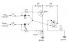
Using a converter eliminates the need for additional lamps on the trailer. Converters are commerically available at most trailer and/or boating supply houses. Or... you could build your own using a circuit like this one. I don't recall the original source of this basic design, but I have updated and clarified it, and I have added the standard trailer wire color codes as well.


I was encouraged to see a post here that would help me combine the brake signal with the turn signal on my tow
vehicle so that it outputs to a common 4 prong plug, but ChrisP's post from May 2004 has a broken link
to his circuit. Darn. The situation is exactly as he describes. This just combines the brake and turn funcitons
into one bulb. It is a logical XOR gate.

I came up with the attached design by piecing together various sources and ideas, and I think it is good in
concept, but when it comes to actually picking the components and connecting them on a breadboard, that is
where I am having difficulty. For some reason, although my simple circuit has only 9 components, controllers
like this sell for $35 to $200 and have a boatload of stuff in them. Of course the store bought ones work
and mine doesn't...LOL

In this diagram, only half the total is shown; it would be duplicated for the left turn, and the running light wiring
doesn't need to be a part of it at all.

I don't have a good grasp of exactly the difference between MOSFETS and BiPolar transistors, and I don't think I know for sure the difference between n and p channel components either.
I am not sure I understand why MOSFETs have source/drain/gate and why bipolar transistors have base/collector/emitter.
I read a post by Roff who once suggested using a p channel in a 12 volt controller when it is desired to put
the load between the circuit and the ground. That is how it wants to be for trailer lights: the ground is always
there and it is the +12v that gets switched.

Here are the values that I chose:
R1 = R2 = R3 = 33K ohm 1/4 watt 5% resistor
R4 = 10K ohm 1/4 watt 5% resistor
D1 = D2 = 3 amp 400 PIV rectifier diode #276-1144
F1 = F2 = 5 amp quick blow fuse
L1 = #1156 trailer light bulb draws 1.5 amp
FET1 = FET2 = n channel 60 volt MOSFET IRF510 Power #276-2072
FET3 = TIP42 Transistor 65watt PNP silicon #276-2027

You may ask "why is R4 there?" Becasue my first attempt at building this used the same FET3 as the others, and it
smoked when I applied the brake. I might have had the source and drain mixed up though. So I changed FET3 to a
p-channel at Roff's suggestion to someone else, and threw another resistor in there to burn off some of the gate
voltage? I don't know what I am doing.

The second time around, which is how it is currenly drawn and specified, blew F1 when the signal was applied. Do I
have the source and drain mixed up on FET1 and FET2? I would be surprised that would blow a fuse.

I thank anyone who can give me some advice on this.
Andy
 

Attachments

  • trailer diagram.jpg
    trailer diagram.jpg
    24.8 KB · Views: 2,756
I haven't analyzed your circuit beyond noticing that your FETs are upside down. The Drain and source need to be interchanged, otherwise the body diode is always forward biased...
 
So I changed FET3 to a
p-channel at Roff's suggestion

No you didn't, you changed it to a PNP BJT.
I'm all for your experimentation and interest, but you need to read a few books and get a foundation in all of this. Your experimenting could get expensive and cause damage to not only your transistors but also your car.
 
Thanks MikeMI for confirming my suspicion. In round 3 of my trials I did swap the drain and source feeds for FET1 and FET2. I had always visualized electricity as flowing from positive to negative, but I realize now that isn't really what happens. Electrons move from negative to positive, from ground to the battery. So the symbology used for a diode seems inconsistent to me because it's arrow points from positive to negative. The arrow in a FET points from negative to positive. See what I've learned already... I am so proud of myself.

Thanks ke5frf, I learned that I used the wrong term, bi-polar transistor. Apparently people refer to these as BJT or Bi-Junction Transistors. It seems to me that either way, it should still fall under the umbrella of Field Effect Transistors, but I am wrong. It is more like a bi-junction-diode, but they do say BJT, so I'll pipe down about semantics.

So here is the results of round 3:
Nothing. No blown fuse, no light, no smoke, nada.

I looked at what john1 posted on March 20, 2003; it seems his circuit simply dims the running lights so that the brakes add to their brightness when activated. I don't accept that as a solution.

Sebi's post from March 19, 2003 looks like what I need, but I have a hard time reading it. I think he used a 1K ohm resistor between the input and the ground to be sure it is low if it isn't high. Maybe when only one of the inputs is high, the other one isn't really low, but rather undefined.

His diode is a 1N5822 whereas I used 1N5404. It looks like the specs on the one I used, an easily obtained one from Radio Shack, has higher values across the board. That is probably not the problem.

He used an IRF9532 p channel MOSFET whereas I used a IRF510. Hmmm. That looks a lot different. It doesn't look like Radio Shack has anything like it.

He also used an IC, CD4070 to do the xor function. That will be difficult to obtain also. I think that if I can find a place to get these items, I'll just build what Sebi designed.

Does anyone recommend a vendor for the 5 new parts I need?

Thanks, Andy
 

Attachments

  • Trail.gif
    Trail.gif
    174 KB · Views: 1,224
I know the following post is going to sound very sarcastic. I don't mean to be. I just get frustrated when I see someone trying to "design" a fairly complicated circuit and implement it without even having a clue as to the function of the components. If learning electronics design is an interest for you, take a few weeks and months to study the basics and fundamentals. Then, read some more advanced stuff. Then, build a few simple circuits and spend some time studying datasheets and learning what things mean. After severals months of self study, practice, and experimentation, you MIGHT be able to tackle this project with at least a clue as to what you are doing.


"Thanks ke5frf, I learned that I used the wrong term, bi-polar transistor. Apparently people refer to these as BJT or Bi-Junction Transistors. It seems to me that either way, it should still fall under the umbrella of Field Effect Transistors, but I am wrong. It is more like a bi-junction-diode, but they do say BJT, so I'll pipe down about semantics."

1), No, a BJT is called a Bipolar Junction Transistor
2)Bipolar Junction Transistors (BJTs) have NOTHING to do with Field Effect Transistors. There is no umbrella to fall under. They are two different technologies and operate totally differently. BJTs are current controlled devices. FETs are voltage controlled devices. BJTs require current limiting resistors and often biasing at the Base-Emitter junction. FETs often require pull-up or pull-down resistors at the Gate-Source Junction to set a default input.

The design considerations of BJTs and FETs are often worlds apart in a variety of ways. They aren't interchangeable.

"I think he used a 1K ohm resistor between the input and the ground to be sure it is low if it isn't high"

If you are referring to the hand drawn schematic on your last post, I think you have it backwards. The 1 kOhm resistors look like pull-up resistors to me, with the NPN BJTs pulling the gate voltage of the FETs to ground when they are switched on.

"Maybe when only one of the inputs is high, the other one isn't really low, but rather undefined."

Are you talking about your schematic at the top? You don't have anything defined except the brake and turn signal voltages. You have the FET gates floating when no voltage is applied.

From your first post..."I don't have a good grasp of exactly the difference between MOSFETS and BiPolar transistors, and I don't think I know for sure the difference between n and p channel components either.
I am not sure I understand why MOSFETs have source/drain/gate and why bipolar transistors have base/collector/emitter."

Then what are you doing here? It is one thing to build a circuit with paint by numbers exactly as a kit or instructional describes, but you can't willy nilly throw circuit components in and out not knowing their complete function and expect results.

"His diode is a 1N5822 whereas I used 1N5404. It looks like the specs on the one I used, an easily obtained one from Radio Shack, has higher values across the board. That is probably not the problem."

Huhhhhhhh????????
His diodes are Schottky diodes. Yours are general purpose rectifiers. Do you know the differences, the applications? You do realize that just because a component has higher values on a datasheet that doesn't make it the right one for the job? You are right, it probably isn't the problem. It is just one of many.

"He also used an IC, CD4070 to do the xor function. That will be difficult to obtain also. I think that if I can find a place to get these items, I'll just build what Sebi designed."

Good idea! And no, none of these parts are difficult to obtain with an internet connection.

Try Digikey, Mouser, Newark, to name a few.

"Does anyone recommend a vendor for the 5 new parts I need?"

I suspect you may need more than 5 new parts.

Go back to my earlier post. I encourage you to try and build the circuit that you are linking to, the one drawn by someone else. Throw away the one you posted earlier. It is a mess. I could almost draw a bunch of components on individual pieces of paper, shake them in a bag, and dump them on a table and wind up with a more workable circuit.
 
I had to come back to this thread and pick on it a little more :)

I'm not picking on you to be mean, I genuinely think it is great that you are trying to learn about electronics. Its just I read your two posts and saw SO MANY indications that you were in over your head. But more than that, and this is the main reason I'm picking on you, while your intentions are good I don't see any awareness of potential consequences. Electricity is something you have to respect in order to properly work with it. You are very lucky that you haven't done serious damage to your vehicles wiring.

"I had always visualized electricity as flowing from positive to negative, but I realize now that isn't really what happens. Electrons move from negative to positive, from ground to the battery. So the symbology used for a diode seems inconsistent to me because it's arrow points from positive to negative."

The symbology used for diodes does not conflict with its function. The direction of the arrow is not indicitive of electron flow, it is indicitive of the anode and cathode and is used to properly bias it in the circuit. The labels "positive" and "negative" are human assigned concepts. There aren't little positive symbols and negative symbols on the subatomic particles. Yes, electrons flow from negative to positive, but an electric current is made of both "negatively" and "positively" charged particles being exchanged in oposite directions. Take your pick as to which one to go by. Conventional current flow is the standard used in circuit schematics, so train your mind to read from positive to negative. The direction is non sequitar, as long as you are consistant.


"The arrow in a FET points from negative to positive. See what I've learned already... I am so proud of myself."

No it doesn't, it points away from the P material toward the N material.

"It is more like a bi-junction-diode, but they do say BJT, so I'll pipe down about semantics."

It isn't semantics, it is literal design, function, and characteristics. Building a circuit isn't like building a wood toy with popsicle sticks.

"So I changed FET3 to a
p-channel at Roff's suggestion to someone else, and threw another resistor in there to burn off some of the gate
voltage? I don't know what I am doing."

LOL!!! "Threw" a resistor in there? A dash of this, a smidgeon of that, season to taste :)

Resistors do not burn voltage, they resist current flow.

The last statement in bold should have stopped you dead in your tracks.
 
I just spent about an hour trying to type up an honest evaluation of the flow of your circuit idea, considering how it was supposed to work, even with the third transistor substituted with a P-channel FET, and ignoring all of the technical errors. I cannot see any configuration in the "design" that will result in the proper switching of the lamp.

The only time your lamp would be on, considering a P-channel in FET3's place, would be when both Brake and Turn are applied, and then it would only blink. Any other combination will produce nothing. And that is assuming you had everything biased correctly and the proper components.

It appears as if you were making some kind of attempt at a logic gate, but have woefully errored. Where did you get this idea from? How did you come up with the bare bones of it? What led you to try this combination?
 
Hi ke5frf,
No offense taken here; I have thick skin. Clearly this is a subject that is dear to you, and I am just kicking it
around for fun. Sorry. I have learned a lot already, I'll probably end up spending around $40 by the time I'm done, and
2 or 3 weeks too. My friends here think I am nuts for not just buying the one from Hidden Hitch for $35 and being done
with it. Oh well, that's just my style, but after 40 years of living like that, you would be surprised the various
topics I have dabbled in.
Your suggestion to use Newark for a parts supplier is a good one. They were the only one of the three you mentioned that
had all nine parts I need. I was really surprised at the cost of the p-channel MOSFET. $8.75 are you kidding? It wasn't
even the one that Sebi designed. Apparently his 2003 design uses obsolete parts. I also had a hard time reading
his hungarian handwriting. A friend I know who works at a motor controller company said that "4k7" means "4.7K"
...and those europeans cross their 7's, but I knew that from a trip I took to France once.
I am attaching a list of the parts that I ultimately chose. What do you think?
Thanks for your time and assistance, your internet acquaintance, Andy
 

Attachments

  • orderform.jpg
    orderform.jpg
    215 KB · Views: 430
OK, I looked over your bill of materials and a few things you should be aware of.

The HC logic series IC you picked for the XOR function is rated for 85degC maximum recommended serivice (HCF). That should be plenty, but being in an automotive circuit exposed to outdoor operating temperatures in a circuit with load currents over an ampere, I might have considered the HCC version. Under normal operating conditions this shouldn't be a big deal, 100 F is only 38 C for reference...plus the load is indirect in the circuit, but robustness is always a good idea in automotive applications. Also be aware that the HC family is a progression in design from the old 74 series TTLs. Your CD 4xxx series was an intermediate CMOS chip, and the HC series was designed for better CMOS-TTL compatability. I wouldn't think you'll have any issues here with driving the NPN from the XOR, or setting the XOR inputs high/low with your signals, but be aware that you are driving a BJT from a CMOS product.

Also, go into this fully aware that this is a hand drawn schematic you plucked off of an internet chatroom. It may be super-duper and I see no reason why it shouldn't be.

Oh, one very important note. I don't know how your last project was set up, but be aware that your FETs need to be adequately sinked.

Take note that your BC182 transistor (TO-92) has inconsistant pin configurations. Pin numbers aren't specified in the hand drawn schematic, so this is a good example of knowing the orientation of your B-E-C pins for your particular transistor. Be very careful with datasheets, all of the characters in the part# are significant.
 
Project Update:
I got the parts that I ordered from Newark.com. They were good; I would recommend them as a supply place. I designed an arrangement of the circuit so that it could be made on a single sided PCB with no jumpers. I tried half (because it is a mirror image kind of logic circuit, one for the left and one for the right) of it on my breadboard with success, and I was delighted.
Then I built the whole thing on a 25 x 15 hole board from Radio Shack. I had a hard time dragging solder along my designed traces, and so I used jumpers on the backside anyway. When tested, I found that only half of the circuit worked. I decided that I probably got one of the BJT BC182's too hot during the soldering, so I went down to R/S and got a BJT 2N3904 to replace it. Like you said, the base and collector pins are swapped, so that made it akward to put onto my board which was designed for the european transistor; but it went in with a careful twist.
Upon another test, I found that the circuit does work on both sides, but the one side that did not work before now works poorly. Instead of completely interrupting the brake input for the signal input, it just dims the bulb a little bit. The other half is perfect. So I figure there must be some slight value differences in the currents and potentials through the substitute transistor that are leading the MOSFET to act like an amplifier rather than in it's desired full saturation switch mode. I tested every component both ways with my multimeter and got substantially similar results in every case. For example, one pair of test points might read 4.68K ohms on one half of the circuit and 4.72K ohms on the other half. I figure that is within allowable range of deviation. Also, the tests across the BJT's were consistent when I set the multimeter to diode testing mode.
My next experiment will be to change and maybe improve Sebi's design as follows:
1) Tie pins 8,9,12,&13 (the unused inputs to the quad XOR gate) to Vdd. I think that unused inputs should not float lest they affect the proper operation of the remaining gate?
2) Add three more 1N4148 diodes to the inputs of the IC. The specifications say that Vi is best if it = Vdd, although a Vdd +0.5V is allowed. Adding these diodes will bring Vi down to Vdd since Vdd goes through a diode.
Any other thoughts? Anyone?
Andy
 
to ke5frf regarding subatomic action in electricity

Understanding just enough to babble on about a topic now and then, I must address your comment regarding electron flow. You said, "Yes, electrons flow from negative to positive, but an electric current is made of both "negatively" and "positively" charged particles being exchanged in oposite directions."

The only "particles" moving are electrons. there are no other "particles" moving directionally in an electrical current. Positively charged particles are not moving at all. There is a surplus and a deficiency in electrons in a group of atoms. When they are connected, the imbalance creates the movement of electrons, and ONLY electrons, toward the DEFICIENCY in electrons (deficient relative to other side of the circuit where there is a greater concentration of electrons) from the "surplus" of electrons. That's where the whole debate of which way is electricity flowing is concluded. Electrons flow from a surplus to a deficiency. They sort-of bump along, but don't necessarily jump the entire length unless others ahead have done so first. It's a freaking CONGA line of electrons, all moving along a wire like a crowd down a hallway. And like a freight train, starting up and slowing down, there is a slight jostle in the knuckles between each box-car, but as soon as the train pushes or pulls, the whole train moves. The electrons act much the same as these box-cars as far as movement at one end being transferred almost immediately down the entire length of the RR track or electrical wire.

Another analogy is people standing shoulder to shoulder, passing pails of water, a source at one end and a deficiency at the other. The water represents electrons. The people do not move, and the deficiency in water does not move to the supply, as in your statement that positive particles move toward negative.

Positive particles do not move to deliver their "positivity" - they merely attract electrons, which we humans have arbitrarily identified as having a negative charge.

I hope this clears up the subatomic topic of electron flow.

Regards,
Joelectron
"I wish I'd gone to college - I'd then be able to say the same things with less understandable words..."

One thing that stumps me in my 5-wire (Ground, tail, brake, right signal, left signal) to 4-wire ((ground, tail, brake/left signal, brake/right signal) converter's circuitry, though, is how the trailer signal light is on opposite to the flash of the car's signal. It looks cool, but I need an "ah-ha" moment with a schematic to understand that.
 
Status
Not open for further replies.

Latest threads

New Articles From Microcontroller Tips

Back
Top