Continue to Site

Welcome to our site!

Electro Tech is an online community (with over 170,000 members) who enjoy talking about and building electronic circuits, projects and gadgets. To participate you need to register. Registration is free. Click here to register now.

  • Welcome to our site! Electro Tech is an online community (with over 170,000 members) who enjoy talking about and building electronic circuits, projects and gadgets. To participate you need to register. Registration is free. Click here to register now.

traffic signal help

Status
Not open for further replies.

frantik101

New Member
ok im new with the electronics so plzz give me solution of this....
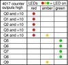
i have this attached circuit diagram of traffic signal... and its working f9 , i have checked it... the main problem is i want to add a digital counter that will perform the countdown action for switching of LEDs.... so how to attach it and WHERE ( i mean on what pins do i have to attach ) ????

PS : a helpful circuit diagram will be really appreciated :)
 

Attachments

  • trafficlcd.JPG
    trafficlcd.JPG
    24.8 KB · Views: 177
Last edited:
Do you mean that you want the output of your new digital counter to switch the Traffic signal LEDs?

If so, disconnect the wire between pin 3 of the 555 and pin 14 of the 4017. Feed the output of your external counter into pin 14 of the 4017. Caution: the voltage level of the output of your counter must look just like the signal that now comes out of the 555; i.e. near 0V for a LOW, near 9V for a HIGH, nice clean rising edge. It would help if your counter runs on the same battery (9V power supply?) as the traffic signal counter.
 
Last edited:
first of all thanks for replying... secondly what im trying to say is i have to attach something that will perform countdown of time... like for how many seconds red LED is goin to be on and after that the counter automatically resets and countdown the time of amber LED... then it coundown the time of green LED... then again red LED and goes on .... you got my point ?? now what u have replied above , will it perfom this kinda action ???? if so then thanks alot.... but if not then plzzzzz help me bro i have to submit this project by monday... :(
 
i have just started my engineering so i have no knowledge about micro controllers..... just heard the name alot... probably we will be taught about it in next year... but if u give me a circuit diag... i will buy components and assemble them.... thats all i can do uptill now and thats only in my knowledge that how to connect circuits by seeing circuit diagrams.... im newbie :(
 
How do you propose to set how long the Red/Green/Yellow LEDs are on?

Can you use three potentiometers, one per color? (Analog method)

DigitalThumbwheel switches? Rocker switches? (Digital method)

If digital, how much resolution for each period?

If digital, can the desired periods be described as R*p, G*p, Y*p, where R,G,Y are integers and p is a period like 3 seconds?
 
i used 1 M ohm potentiometer to set the time.... and connected the LEDs in such a way that time period will be in a ratio of 5 : 1 : 4 .. i.e
red : amber :green ... as it can be seen that i have connected green with 4 outputs , amber with 2 outputs and red with divide 10 output (12 pin) which means output to be high on 1st 5 pulses.... i connected amber with 2 outputs in such a way that after red led , amber and red both will be on... but after green led only amber will be on when loop is restarted.... see the attached table for how its working....

for example if i set the potentiometer to 300k then the red LED is on for 20 sec , (red and amber both at same time) are on for 5 sec... and green is on for 20 sec

if i change the value of potentiomenter to 500 k
red led is on for 40 sec (supposition)
red and amber will be on for 10 sec
green will be on for 40 sec
 

Attachments

  • trafficlseq.JPG
    trafficlseq.JPG
    14.9 KB · Views: 126
Last edited:
i used 1 M ohm potentiometer to set the time.... and connected the LEDs in such a way that time period will be in a ratio of 5 : 1 : 4 ..

So what do you want to change?
 
Hi MikeMl, I think you didn't get what he mean exactly. He wants a seven segment count down time display for the time intervals. It'll reset and again start counting down for each signal output.
 
Status
Not open for further replies.

New Articles From Microcontroller Tips

Back
Top