Continue to Site

Welcome to our site!

Electro Tech is an online community (with over 170,000 members) who enjoy talking about and building electronic circuits, projects and gadgets. To participate you need to register. Registration is free. Click here to register now.

  • Welcome to our site! Electro Tech is an online community (with over 170,000 members) who enjoy talking about and building electronic circuits, projects and gadgets. To participate you need to register. Registration is free. Click here to register now.

traffic light help SOS

Status
Not open for further replies.

reila

New Member
hi everyone,
i am currently pursuing my first year in electrical and electronic engineering. a project was assigned to me and i am facing some problems which i really can't solve. it would be a great help for me to have some advices from experienced members in this forum. i have to present it on thursday(5th Nov) and had been working on it for two weeks but still ended up with a problem.

the question requires to build a four way junction with four traffic lights. each junction must be able to take the left or right turn and go straight when the traffic light is green, which means only one traffic light can turn green at a time.

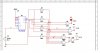
my design was initially 3 bits using JK flip flop. i used three JK flip flop and designed it on multisim. multisim shows that it works well. unfortunately when i work it out on the breadboard, the JK flip flop couldn't run according to the sequence. for example, it couldn't go from 000 to 001 to 010 to 011. instead it goes from 000 to 010 then to 0001 then to 011. i couldn't understand why but my friends suggest to use counter since JK flip flop doesn't work.

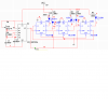
now that i am using a 4 bits counter, the traffic light does work on breadboard. the problem encountered at this point is at 0010, for the first traffic light(R1Y1G1) both yellow light(Y1) and green light(G1) are simultaneously lighted up. even in multisim. it happens to each traffic light for both green and yellow light. i was using the first traffic light as an example. anyone mind helping me out?? my truth table for the traffic light is as follow:

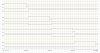
DCBA R1 Y1 G1 R2 Y2 G2 R3 Y3 G3 R4 Y4 G4
0000 0 0 1 1 0 0 1 0 0 1 0 0
0001 0 0 1 1 0 0 1 0 0 1 0 0
0010 0 0 1 1 0 0 1 0 0 1 0 0
0011 0 1 0 1 0 0 1 0 0 1 0 0
0100 1 0 0 0 0 1 1 0 0 1 0 0
0101 1 0 0 0 0 1 1 0 0 1 0 0
0110 1 0 0 0 0 1 1 0 0 1 0 0
0111 1 0 0 0 1 0 1 0 0 1 0 0
1000 1 0 0 1 0 0 0 0 1 1 0 0
1001 1 0 0 1 0 0 0 0 1 1 0 0
1010 1 0 0 1 0 0 0 0 1 1 0 0
1011 1 0 0 1 0 0 0 1 0 1 0 0
1100 1 0 0 1 0 0 1 0 0 0 0 1
1101 1 0 0 1 0 0 1 0 0 0 0 1
1110 1 0 0 1 0 0 1 0 0 0 0 1
1111 1 0 0 1 0 0 1 0 0 0 1 0

(edit : p/s R1= red for traffic light1, Y1= yellow for traffic light2 and so on)

to sum up, i have two questions :
1. why does the JK flip flop doesn't run according to the sequence?
2. what may have caused the yellow and green light to be lighted up simultaneously?

hereby would like to thanks in advance for any help. thank you.
 
Last edited:
1st you drw a timing diagram for all lights for easy understanding. then you can specify the sequence of lights to be ON. then you see how many state you require to run one cycle. that time your counter should reset. also you have to implement delay or time diffeences in ON time ex: yellow always On very short time abd green some more time and the red for very long.

another way to design is select complementy logic from other lights, ie you will only operate only greens and yellows, but the red would get signal from inverted green of the rest, ie if there will be a green light is on the rest of all reds would remain off.

there are lot of ways to design it, you ca try few. also you can somply use binary counter 4017 in series so that can have a good cycle and trigger the lights individually.

if you post your complete diagram its easy to tell where u made mistake.

razeen
 
hi Razeen,
thank you very much for your reply.

i like your idea of inverting greens to red. :):)will give it a try.:D

i specify my sequence using truth table. for the first traffic light(R1,Y1,G1), 0000,0001,0010 are green; 0011 is yellow; and the rest are red.

the attachment is my circuit for one traffic light(R1,Y1,G1) in jpeg. i wanted to attach along the multisim format but is invalid.
from my truth table, the simplified equations are as follow:

R1 = C + D

Y1 = D'C'B A

G1 = D'C'B' + D'C'A'

R2 = C' + D

Y2 = D'C B A

G2 = D'C B' + D'C A'

R3 = D' + C

Y3 = D C'B A

G3 = D C'B' + D C'A'

R4 = D' + C'

Y4 = D C B A

G4 = D C B' + D C A'
 

Attachments

  • traffic light.JPG
    traffic light.JPG
    41.1 KB · Views: 5,070
why make it so hard??

do what mbarazen suggested, just a 4017 add some inverters and your done, at least it sounds easy as it should be.
I'm a little confused on your description.
only one green light of the four?
lets label the lights N, S, E, W (compass headings)
N=green
S = yellow or red?
E & W = red
just allow traffic to go from one traffic light only then alternate
N ,S then E, W
a timer to sequence the 4017.
making something more complex than it needs o be will lead to frustration and/or failure.
 
hi MrDEB
thank you for replying.

sorry for confusing.
when the north traffic light(N) is green, east(E), west(W), south(S) traffic lights have to be red. when N turns yellow, E,W,S remain red. when N turns red, E turns green, W,S remain red. and the cycle goes on.

i just started my course and am very ignorant of most components.
regarding the 4017, i don't know how to use it. i can't find it in multisim. so far, we were taught to use limited 74LS only. i checked the datasheet and it has a Vdd and a clock inhibit. may i know wat are these supposed to be connected to?
Vdd = power supply (like Vcc on a TTL chip). Vss = ground.

Clock inhibit (or clock enable) causes the chip to ignore the clock signal when set high (or low, check the datasheet).
 
if having to use only 74ls

then 74150 = 1 of 16 data selector
2 of the 74151 = 1 of 8 data selectors
or
you could go with a BCD to 1 of 10 outputs = 74154
for simulation I recommend LT Spice. some what of a learning curve but lots of components to choose from or download.
easy way to see what is happening is simulate 2 - 74ls74s configured as a ring counter but you only need 3 outputs.
RED, YELLOW GREEN
get one built then multiply by 4 umber of circuits.
 
this might give you some ideas?

its a start using 74ls74's
you just need to add more LEDs use transistors to run the 4 LEDs per output.
outputs I think are
out #1GREEN, YELLOW RED RED
out#2 RED GREEN YELLOW RED
out#3 RED RED GREEN YELLOW
out#4 YELLOW RED RED GREEN
in other words put 4 leds per 74ls74
I didn't put the sim right but then maybe you can figure it out??
Its so close to what your looking for.
HINT look at the data sheet for the 74ls74 and see what it will sink and go from there.
 
why no attachement??

the LEDs should be in series but caculate using the forward voltage etc.
wrong file type
If you do the series resistors then you only need 2- 74ls74s and one 555
 

Attachments

  • traffic signal.PNG
    traffic signal.PNG
    30 KB · Views: 2,056
timing diagram

see the timing diagram attached for your project, I assumed green would be on for 20sec and yellow would be for 2sec, thus red would be on for 66sec.

now see the points where values maked on x axis, those are the points the system need a state change. You have to build your circuit so that at 0th sec G1 would tun on and latch, it will fall at 20th second same time yellow will goes to on, then after 2sec red.

what you need is a counter and some logic that would give a single output when at the times 0,20,22,42,44,64,66,86 and 88 seconds then reset.

take this out put and trigger latches to make on and off for individual lgihts. Hope it would work. As others sugested you can design your circuit

to further simplify you can have your counter only to cycle every 22 sec, then use another counter to count reset signals of the 1st one and it would have 4states and would enable the groups of lights for each sides. ( ie 22x4)

i better post you a simple diagram for complete circuit when i find enough time.
 

Attachments

  • timing diagram.JPG
    timing diagram.JPG
    171.3 KB · Views: 1,388
Last edited:
your timing data is wrong

the flip flops change states at the same time.
there is no delay.
if the first Q utput goes low then all the others go hige at sametime.
the _Q goes low then all the other outputs go high at same time.
the D flp flops (both) clock at same rate.
unless I have something wrong??
 
There is always a propagation delay, but it is extremely small. Simultaneity does not generally speaking occur in the real world.
 
Last edited:
each cluster of 4, in series LEDs (4 clusters)

will be connected to the 4 outputs of the 74ls74
so only one 74ls74 is required.
both are clocked at same time.
 
complete circuit using 4017

Hi,

i have sketched a circuit for him, hope it may work, i used 4017 instead. but the idea is to get two signals from the counter one is at 18th second and other is at 20th second (since i used only one 4017 for primary counter i decided the time as so, if more time required two 4017 can be cascaded).

there is another slave counter to switch or enable all for set of lights and resets every 5th cycle of the primary one.

74ls74 also could be used to do the same with some logic connected.

so it will work as follows.

once the green is on it will remain on for 18 second then yellow wil turn on for 2sec, then red will remain on for the rest of the time until other set of reds and yellows complete it cycles.

if any one can post him with 74ls74 togethe with the idea instead of using 4017? i am pretty bc and couldnt spend much time.
 

Attachments

  • circuit.JPG
    circuit.JPG
    135.5 KB · Views: 1,951
the timing diagram is for the basic idea of how it has to work (lights), not for a particular design, see my post using 4017, hope it will work as the timing diagram
 
I understood the op was haveing to use TTL only

the 4017 is perhaps the easiset way but the op mentioned only TTL.
or did I miss something.
the clock is to run at 40 hz, never recall a 2 second yellow?
now I is lost
 
for the circuit i posted i started with 2second pulse and decided the time as per convenient. if he uses 40Hz then has to use another step down to get 2sec.

he has used 74la163, in this case what we need is a logic high to tell "On green" another logic is to tell "off green" and "on yellow".

the same idea can work with above two signals together with another 74ls163 counter (as slave one in my circuit)and with some extra logic.
 
why all the extra IC's when just one 74ls74 will do the job??
unless I missed something.
IF the op can use a 4017 then this is a piece of cake
Want a delay (green and red stay on longer?) add a 74ls74 as a divide by 2
 
why all the extra IC's when just one 74ls74 will do the job??
unless I missed something.
IF the op can use a 4017 then this is a piece of cake
Want a delay (green and red stay on longer?) add a 74ls74 as a divide by 2

Mr.DEB,
did you consider he has to use 3x4 LEDs total to make all of them on and off like a real four junction signal light?? or what you are sugestion is only a single Red yellow and green??
 
I never saw where the op wanted 3x4 LEDs
I proposed using separate RED, YELLOW, GREEN LEDs
no real different though???
 
Status
Not open for further replies.

Latest threads

New Articles From Microcontroller Tips

Back
Top