Continue to Site

Welcome to our site!

Electro Tech is an online community (with over 170,000 members) who enjoy talking about and building electronic circuits, projects and gadgets. To participate you need to register. Registration is free. Click here to register now.

  • Welcome to our site! Electro Tech is an online community (with over 170,000 members) who enjoy talking about and building electronic circuits, projects and gadgets. To participate you need to register. Registration is free. Click here to register now.

Traffic Light circuit building problems

Status
Not open for further replies.

oxygen454

New Member
Hey guys I am new to this forum so go easy on me haha.

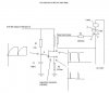
I am building a 3 stage monostable 555 timer circuit for my street light I got off a friend that works for the city traffic control. I have the first part built with 555 ic's that turn one LED on then when timed out, turning the next one on... green, yellow, red. I ran into some problems along the way. I have been all over the net and cant seem to find any answers.

What the circuit does is the 555's send a trigger voltage to the triac which in turn, turns on the AC to the light. The trigger voltage is 9volts from the 555 ic to the triac.

1. First problem is, I want to trigger the AC part of the circuit with a triac but I don’t know how to hook it up and what the pin-outs are. It says 15A/400V …I think the letters/numbers are MRC15 0134 (kind of hard to read small print). I originally thought that the middle was the low voltage trigger and the left and right pins were the higher voltage leads but I haven’t had it working. I tried it on 9 volts before using 110vac and blowing everything up haha!

2. My transformer is a 650-122 12VCT 2Amp with 2 wires for AC and 3 out for DC. How do I hook this up?

3. How can I get 9 volts after the transformer to run the 555’s? I have the circuit built for 9 volts and was wondering if I could use a resistor off the transformer to lower the voltage from 12 to 9?

Any help would be much appreciated!! I am going to build a website on this when I am done if not before.
 
1. I believe the 555 is rated to 15V, check for yourself, but I am almost certain that it is, so you dont need to drop the voltage to 9 volts first.

2. Triacs have a minimum gating current. The gate looks like a forward biased diode, so you need to figure out what the gating current should be and put an appropriate resistor between your trigger and the triac gate pin.

3. Most triacs I have used have pins 1 and 2 as the AC and pin 3 as the gate in a TO-220 package.

4. Your transforer has a center tap, so its DC output is 12-0-12. You could use just the two like colored wires to get 24V, use the two like colors in parallel to get 2x as much current at 12V, use only one side to get just 12V.
 
Thanks for the information. I just have to find out the configuration of this triac. I believe the store I bought it from has a diagram for it, not sure. I also read that the 555 will run up to 15 vdc, so does this mean I dont have to raise my resistor values on the circuit?

Thanks for the help!
~Chris~
 
If your circuit is 12V as you indicated then yes, you dont need to drop the voltage (and btw, a resistor would not be the way to do that). But you have a 24VAC center tapped transformer. If you use half of that, you will have 12VAC. But this is the RMS voltage, when converted to DC, it will be somewhere around 16 or 17 volts depending on both the load, rectification method, and filtering capacitors. So you will probably need a regulation circuit of some type to bring the voltage to a consistent level say 12V or so.
 
Hmm I think I am going to get a multi volt plugin type transformer and just use that, it will simplify my circuit and probably cost less. Only problem left is this triac but I might go to relays. The only thing with relays are that they are noisy and triacs are silent. Will play with it till I figure something out. Is there a place on the net or some way I can figure out the pin outs on this 3 pin triac that you guys might now of?

Thanks,
~Chris~
 
I posted the pinout in item 3 a few posts back?

3. Most triacs I have used have pins 1 and 2 as the AC and pin 3 as the gate in a TO-220 package

If you want to be certain of your triac, you should post the complete part number or look it up on the manufacturer's site.
 
Yeah thanks I saw that and it has helped, I am playing with it now and when 1 and 2 are AC ... and 3 is trigger... I add power and it turns on right away, when I trigger it it turns off?? Weird, maybe try some other configurations with the wiring?
 
One more thing, I have grounded the back of the metal thermal tab on the triac does that make a difference and also I am triggering it and running everything as a test on a 9 volt battery, maybe that makes a difference too with the amps and volts? Not too sure. Thanks for your help tho crust I really apprciate it!
 
Okay good news! Got a hold of the store and they said google search MAC15A6 and I got all the info, too much actually haha Im not sure which one fits mine and what the pinouts are just yet.
Link... https://www.onsemi.com/site/products/summary/0,4450,MAC15A6,00.html

What I have tried is using Pin 1 as the IN of 110vac, Pin 2 as the OUT for 110vac, and pin 3 as a trigger for 9vdc. I also tried all this on a powerful 12vdc power supply and still nothing. I am trying to figure this out before I actually hook up the 110volts so I dont level my project if it is hooked up wrong.
Also if Pin 2 is the same as the thermal backing plate and is connected, does this mean the backing plate is live with what ever pin 2 is carrying which in this case will be 110vac? :?

If 9 volts has something to do with it and have to go up to 12 volts then I am wondering if I have to change all my resistors too.

Anyone figure this out? :wink:
 
I may be wrong but .... I dont think that placing 12VAC across the mains terminals of the triac is going to work. The threshold trigger voltage is probably too high. You will get very little output from your triac (You should be able to see it with a scope however).
 
Okay got enough guts to try the real deal with 110vac and 12vdc. I used a inline fuse and a long extenstion cord incase I had to yank it out of the wall hahaha.

The triac only turned on for a split second when I triggered it but it would not stay on. Something is not right? Not sure what to do, might eventually give up and use relays but they are noisy but will work.
 
I've had a look at your circuit and there seems to be a couple of bits missing. :shock: The ac common (white) should be connected to the (ground) of your circuit, which shouldnt be connected to real ground at all. better call it common. Without this there is no way to complete the circuit for the trigger current, and the triacs will not fire. The fuses in the gate leads should be resistors, 390R should be good. Without the resistors the triac gates will draw a lot of current and the 555's may die. There is no way to start the sequence, it is possible for all the 555's to be off. A push button switch from R1/pin2 to common would start the sequence. I don't know if you are aware of the different operation of triacs on ac and dc. Once triggered, a triac will stay on until the current through the device is interrupted. On dc this means that the triac will stay on until you switch off. On ac the triac will stay on until the supply goes through zero (60 Hz).
PLEASE USE AN ISOLATING TRANSFORMER :!: :!: Sorry to shout but a nasty shock is best avoided. Hope this helps :lol:
 
Thanks for your help! I am somewhat aware how triacs work but I have learned a lot more from what you have wrote. I wasent sure if I had the right kind of transformer but I have changed it for a multi purpose transformer that replaces things like batteries in house hold electronics. Like a multi adapter. Just made my life easier haha.

I tried hooking the triac up to ac and dc the other day but the light just flickered. I took the left site of the ac lead and the right side and hooked it up to the triac with a light inbetween. Will reistors work as well as fuses do or should I have both? Not sure. Im trying relays as well to see how they might work and how noisy they are.


Thanks again for all your help!!
Chris
 
Thanks a million, the light works just as I wanted it to! I used replays instead of the mosfets and the triacs which worked well and also a multi setting and multi adapting power supply that you can buy for things like walkmans which worked well.

Only thing left is to figure out what kind of variable resistor I can use for the timing. Im not sure how to figure this out or what to use. But thanks again and finishing notes on this will really help! Thanks again!
 
Triacs are designed to work with pulsing trigger, that means you shouldn't connect it directly to the 555 and that's why all triacs triggering uses a opto or transformer interface.
The triac trigger should be done by spikes of curret and because you are switching AC (60Hz), it have to be triggered many times every cycle.
The circuit attached was designed to generate the triggering pulses.

By the way, the symbol you are using for triac in fact is a XOR gate.

If I was you I would use three small relays. Would work the same way and you could save couple $. Pulse transformer cost a bit.

Nilo
 

Attachments

  • UJC.JPG
    UJC.JPG
    28 KB · Views: 617
An update from a few years back. I did end up using the relays, thanks! They worked great. Wow this is old lol
 
Status
Not open for further replies.

Latest threads

New Articles From Microcontroller Tips

Back
Top