Continue to Site

Welcome to our site!

Electro Tech is an online community (with over 170,000 members) who enjoy talking about and building electronic circuits, projects and gadgets. To participate you need to register. Registration is free. Click here to register now.

  • Welcome to our site! Electro Tech is an online community (with over 170,000 members) who enjoy talking about and building electronic circuits, projects and gadgets. To participate you need to register. Registration is free. Click here to register now.

TPA3122D2N in SE mode, one channel removed?

Status
Not open for further replies.

joecool85

Member
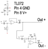
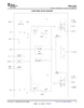
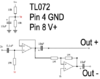
I'm looking at building a TPA3122 circuit for use as the power amp section of a small 12v battery guitar amp. It would give me 5w at 4ohm which is perfect and at 90% efficiency. I've always wanted to do a class D and this chip seems like the right one. The one issue is that I only need one channel. Rather than build out both channels just to shunt one, can I remove the output caps, resistor, and filter from the right channel and then shunt to ground? I've attached an image of the original circuit from the datasheet as well as my proposed version.

Of note, I had thought about going BTL, but the biggest concern is that it would require even more parts because I would need to use a SE to differential converter in front. That and the SE mode provides the power I need at the voltage I can provide (12-14v.)

Thanks for any insight!
 

Attachments

  • tpa3122d2n-se.jpg
    tpa3122d2n-se.jpg
    145.3 KB · Views: 183
  • tpa3122d2n-se-mono.jpg
    tpa3122d2n-se-mono.jpg
    100.6 KB · Views: 179
You certainly MUST NOT short the output to ground like that! :nailbiting:

It would make a lot more sense to bridge it, and get 8W in to 8 ohms - the difference would be well worth it.

As for 'more parts', you're over complicating it with " SE to differential converter in front" - all you need is a simple inverter on one input, just a single opamp in inverting mode - and you will of course save the 470uF coupling capacitor as well (which seems a bit low anyway).

Nigel, that's what I get for posting this in a hurry. It was suppose to send the right channel into an 8ohm resistor.

Regarding BTL mode and differential inputs...are you saying that I could split the signal coming out of the preamp and run it straight into the left input, then connect in parallel to the left input, a TL071 set as inverter and push it's output to the right channel input? It seems to easy. I wouldn't need to use an opamp to split the signal before doing this?
 
Nigel, that's what I get for posting this in a hurry. It was suppose to send the right channel into an 8ohm resistor.

No need, and no use for it - simply ground the input (before the capacitor! - as shown on your diagram), and forget about it.

Regarding BTL mode and differential inputs...are you saying that I could split the signal coming out of the preamp and run it straight into the left input, then connect in parallel to the left input, a TL071 set as inverter and push it's output to the right channel input? It seems to easy. I wouldn't need to use an opamp to split the signal before doing this?

That's right, you just need a simple inverter feeding one input - bridging is really VERY simple.
 
No need, and no use for it - simply ground the input (before the capacitor! - as shown on your diagram), and forget about it.


That's right, you just need a simple inverter feeding one input - bridging is really VERY simple.

I had read that if there isn't a load there can be "ringing" in the circuit and cause it to burn out, is that not the case?

Also, I was thinking about using an opamp buffer at the front. In my head I'm thinking a TL072 could be a unity gain buffer on the first half, then inverting on the second half. Tap the left input of the TPA3122 direct to the buffer output, and the right channel to the inverted output. That said, I haven't found an example of someone using a TL072 or similar as both inverting and non-inverting like this. Would this work, or would I need two separate chips?

Thanks for the help, Nigel!
 
Last edited:
I had read that if there isn't a load there can be "ringing" in the circuit and cause it to burn out, is that not the case?

No it should be fine - if you want to be 'careful', you could always stick a higher value resistor across as a slight load.

Also, I was thinking about using an opamp buffer at the front. In my head I'm thinking a TL072 could be a unity gain buffer on the first half, then inverting on the second half. Tap the left input of the TPA3122 direct to the buffer output, and the right channel to the inverted output. That said, I haven't found an example of someone using a TL072 or similar as both inverting and non-inverting like this. Would this work, or would I need two separate chips?

There's no reason not to use the two halves of a TL072 as inverting and non-inverting, I would have said it's probably very common to do so?.

However, there's no reason not to use them both as inverting?, and feed the output of one to the input of the other.
 
No it should be fine - if you want to be 'careful', you could always stick a higher value resistor across as a slight load.


There's no reason not to use the two halves of a TL072 as inverting and non-inverting, I would have said it's probably very common to do so?.

However, there's no reason not to use them both as inverting?, and feed the output of one to the input of the other.

Good point. If they both invert, and one feeds the other, then the signal would be inverted from the left to right inputs. Sounds like this is much easier than people made it out to be.
 
Good point. If they both invert, and one feeds the other, then the signal would be inverted from the left to right inputs. Sounds like this is much easier than people made it out to be.

It's always been very simple :D

However, it helps that you're wanting it for guitar use - where a little distortion isn't a problem
 
I'm using a PAM8302 class D board that I picked up a few years ago for testing purposes. It also requires differential inputs. I have built a TL072 based single ended to differential converter (attached rough schematic). I used ideas from Jack Orman: https://www.muzique.com/lab/buffers.htm

I'm curious if I could trim some of the capacitors out without losing stability. Rod Elliot shows a very similar circuit to mine, but with no capacitors at all: https://sound-au.com/project51.htm (figure 1 from his site is attached). Also Rod's circuit uses 100 ohm resistors at the tail of each leg of the differential output, is this a good idea?

I always thought you needed caps to decouple between sections etc, maybe not? Thoughts on this?
 

Attachments

  • se-diff-converter.png
    se-diff-converter.png
    20.6 KB · Views: 177
  • p51-f1.gif
    p51-f1.gif
    3.2 KB · Views: 204
The capacitors are there to block any DC voltages - if there aren't any (and can't possibly EVER be any), then you don't need them.Very often they are included because you don't know what's going to be connected to it (either IN or OUT). 'Mostly', anything properly designed will include blocking capacitors on the inputs and outputs, so you don't 'need' to - but if you think you don't 'need' to, perhaps they did as well?.

Inside your complete circuit is fine, as you're 100% in control - but external connections should be DC blocked.

The 100 ohm resistors are for if the circuit is directly feeding a long coaxial (screened) cable, and prevent instability. In your case, presumably the splitter/inverter is directly next to the power amp?.
 
Looks like the only cap that might be removable would be the 5pF one on the inverting section which was for "rolloff of frequencies above the audible range". Realistically, does the 5pF really do anything important?
 
Looks like the only cap that might be removable would be the 5pF one on the inverting section which was for "rolloff of frequencies above the audible range". Realistically, does the 5pF really do anything important?

While a tiny value like 5pF looks like it does nothing, the crazy high values of the resistors means the HF rolloff is 30KHz.

Where did the 1M resistors come from? - notice the other example uses 33K - which makes a lot more sense.

If you made the resistors 100K, you could use a 50pF capacitor, or make them 10K and use a 500pF.

You could connect R1 directly to the output of the first opamp, getting rid of the 0.1uF, leaving the 10uF to fed the direct output.

The 1M resistors came from AMZ (Jack Orman), that's what he used. It set the input impedance to about 1M. Given that this will normally be driven by a guitar effect's pedal or preamp, 1M is fine but probably 100k would work without issue. Thoughts?

Regarding the rolloff using the 5pF capacitor, I was thinking about it, wouldn't you want to roll this off on both the sides of the differential? In my example I believe it is only doing the rolloff for the inverted side. Is the rolloff important? Sound wise, no guitar speaker will do anything with frequencies that high anyway.

Last, the coupling capacitors. I like the idea of getting rid of the extra 0.1uF cap on the inverter input. Am I correct that the R1 from inverter section (I need to relabel these, that's what I get for copy/pasting clips of schematics together), would need to connect direct to the output of the first stage - before the 10uF capacitor? I'm thinking so as that should protect both the output of the first stage as well as the input of the inverter stage if someone plugged something into the output that didn't belong there.
 
I've been looking at the functional block diagram and pinout descriptions for the TPA3122D2N. I'm thinking that if I disconnected V+ to the right channel, I could completely remove all pieces of it (input capacitor, bootstrap cap, output resistor/caps/inductor) and not even need to ground in the input. No power, no signal, no problem?

Attached is the block diagram. I'm talking about not sending voltage to PVCCR and not installing the bootstrap capacitor between BSR and ROUT. There is a note in the descriptions of each pin that PVCCR is "Power supply for right channel H-bridge, not connected to PVCCL or AVCC.".
 

Attachments

  • tpa3122d2n-fbd.png
    tpa3122d2n-fbd.png
    41.9 KB · Views: 173
The 1M resistors came from AMZ (Jack Orman), that's what he used. It set the input impedance to about 1M. Given that this will normally be driven by a guitar effect's pedal or preamp, 1M is fine but probably 100k would work without issue. Thoughts?

That explains the crazy values - you can't just stick circuits together that are intended for completely different things.

There's no requirement for a high input impedance, as it's fed from the low impedance output of the previous opamp.

Regarding the rolloff using the 5pF capacitor, I was thinking about it, wouldn't you want to roll this off on both the sides of the differential? In my example I believe it is only doing the rolloff for the inverted side. Is the rolloff important? Sound wise, no guitar speaker will do anything with frequencies that high anyway.

It's to improve stability as well, the rolloff isn't really important.

Last, the coupling capacitors. I like the idea of getting rid of the extra 0.1uF cap on the inverter input. Am I correct that the R1 from inverter section (I need to relabel these, that's what I get for copy/pasting clips of schematics together), would need to connect direct to the output of the first stage - before the 10uF capacitor? I'm thinking so as that should protect both the output of the first stage as well as the input of the inverter stage if someone plugged something into the output that didn't belong there.

Yes, which is why I suggested it.
 
It's to improve stability as well, the rolloff isn't really important.

Does the non-inverted section need anything for stability?

Also, any thoughts on disconnecting power to the right channel and leaving it floating? I'm thinking that it would mean I could omit a resistor on the right input since it wouldn't have power anyway. From the block diagram it seems to me that the left and right channels are separate so it should be ok.
 
Can the TPA3122 be used this way? (from the TPA3100 datasheet)
View attachment 127852

I don't believe so. Regardless, my goal here is efficiency at low wattage (0.5w to 2w or so). Running in SE mode gives me really high efficiency at 4ohm (65% - 80%). It can be run in BTL mode and be bridged, but at the wattage I'm looking at it is yielding 40% - 70% efficiency. Given that the majority of the time I am playing around 1w the SE mode is way more efficient (about 76% vs 55%). If PBTL was possible, it would probably be at about the same efficiency rating as BTL.
 
I wanted to share the functioning SE to differential converter using a TL072. I kept the 1M resistors and omitted the feedback cap. All seems stable and functioning. It works perfectly on 9v, and surprisingly it even works (though distorted) using the 4.2v of the fully charged lipo I'm using to the run PAM8302.
 

Attachments

  • se-diff-converter-v1.1.png
    se-diff-converter-v1.1.png
    16.6 KB · Views: 191
Status
Not open for further replies.

New Articles From Microcontroller Tips

Back
Top