Continue to Site

Welcome to our site!

Electro Tech is an online community (with over 170,000 members) who enjoy talking about and building electronic circuits, projects and gadgets. To participate you need to register. Registration is free. Click here to register now.

  • Welcome to our site! Electro Tech is an online community (with over 170,000 members) who enjoy talking about and building electronic circuits, projects and gadgets. To participate you need to register. Registration is free. Click here to register now.

Touch screen issue!

Status
Not open for further replies.
Hello,

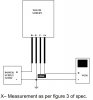
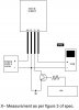
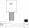
I have a small 4 wire resistive touch screen approx. 2" diaogonal. It believe that the outer edge two wires of the FPC cable are "+". Where as the two other wires are the return signals each in respect with their "+" wire. I am applying 3.0VDC at the "+" wires and trying to read the output voltage on the return wires as I move an object pressing on the touch screen.

The problem is, I am reading a steady 3.0VDC on the return wires no matter where I touch on the touch screen.

Has anyone done this before? If anyone can help, it would be very appreciated.
Thanks

R
 

Attachments

  • TouchScrren.jpg
    TouchScrren.jpg
    35.1 KB · Views: 118
Last edited:
hello again,

I read a document late last night at :

https://www.electro-tech-online.com/custompdfs/2011/10/AN10675.pdf

I tried a few things and got it to work. I tried the "x" axis reading it via the "Y+" output. So I have made a schamatic on how I got it to work, please view attachment "Touch Screen Bias".

Also, the "Y-" can't always just stay open. It also has to be tied to ground when we want to measure the y axis via the "X+" output. So I would need the PIC to control the "Y-" to be at "Open" state at one instance and "grounded" state in another instance. I am Planning to do the circuit outlined in attachement called "touch screen transistor". I have not tried this though... I am not that good at electronics. I was wondering if you can take a look as to weather or not I should proceed this way. I was planning to use a 2n2222 with a 1K ohm resistor!

Your help would be very appreciated. Thanks.

PS. The "touch screen transistor" schematic is just for the X measurement, I would obvioulsy do the same transistor layout for
"X-" !

r
 

Attachments

  • TouchScreen_Bias.jpg
    TouchScreen_Bias.jpg
    58.3 KB · Views: 116
  • TouchScreen_Transistor.jpg
    TouchScreen_Transistor.jpg
    75.2 KB · Views: 116
Last edited:
Basically you can think of a touch screen as 2 variable resistors which you must read twice, one time for the x axis and one time for the y axis.

e.g. you have 5 volts across the x axis (resistor) and nothing on the y axis (it is an output when the x axis is powered). Depending on where you touch it (make contact with the variable resistor) you will get a different voltage (different part of the resistor) directly corresponding with the x position of the touch.

You then 'high impedance' the x axis (set to input) and power the y axis and do the same process again to give you the y position.

I suggest you use an ADS7843. They are so easy to use and do a lot of the work for you. At least read the datasheet, very informative on touch screens.
 
Status
Not open for further replies.

Latest threads

New Articles From Microcontroller Tips

Back
Top