Continue to Site

Welcome to our site!

Electro Tech is an online community (with over 170,000 members) who enjoy talking about and building electronic circuits, projects and gadgets. To participate you need to register. Registration is free. Click here to register now.

  • Welcome to our site! Electro Tech is an online community (with over 170,000 members) who enjoy talking about and building electronic circuits, projects and gadgets. To participate you need to register. Registration is free. Click here to register now.

Toroidal Transformer Inrush

Status
Not open for further replies.
There will be no inrush current if this is not a switching power supply, and the primary is connected directly to mains. A standard fast blow fuse will suffice. Whatever power is being drawn from the secondry, will equal the power drawn from the primary.

Sorry, but you are completely 100% wrong!.

Large toroids have HUGE in-rush currents, even without a load - and with massive electrolytics on the secondary the in-rush is even higher.

An anti-surge fuse, suitable rated, is absolutely essential, and for even larger toroids soft-start circuits are seriously advised.

Even conventional transformers require anti-surge fuses as well, in fact very few items require fast-blow fuses, and we don't even stock them.

BTW, while many TV SMPSU's have surge limiting resistors (particularly the older ones) it's not universal.

The 4.7 ohm was the standard Philips value :p
 
To Nigel Goodwin,
You are right, with a large capacitor and a high current on the secondry, the input will also have a high "inrush" current. Is this because, at swith-on, the AC input could be at its peak, that is 240√2 V? Should'nt the primary inductance prevent a sudden change in primary current (VL = dIL/dt)?
 
Hehehe.
Thanks Nigel/Q5101

Q5, for interest sakes, this is a 12 Amp toroid, used in a 10 A linear supply.

Just out of interest, would a relay system work that has the secondary smoothing capacitors on delay. Meaning, that it brings in each cap with a 0.5 second delay or so?

Either way, I have pretty much come to the conclusion about why the primary only measures 5 ohms, etc, and I will be using a slowblow/A-S fuse on the primary side, not sure what rating yet.

Thanks all for debating this :)
 
A perfect inductor would prevent a sudden change in current. Parasitic resistance would give an exponential rise in inductance voltage (and therefore back EMF), rather than an instananious one, so the in-rush would occur during this exponential rise time (5L/R). Does this make sense?
 
If you want a delay, use a LARGE wattage resistor in the primary, and after a second or so short it out using either a relay or TRIAC - don't do it in the secondary (what would be the point?).

For a fuse I would suggest trying 3.15A A/S - increasing to 5A if it blows periodically.
 
Hey hehehe,
if you don't mind 120Hz half wave rectified power on your supply rails for half a second, no worries. It sounds good, but complex.
 
Hey hehehe,
if you don't mind 120Hz half wave rectified power on your supply rails for half a second, no worries. It sounds good, but complex.

Sorry, I don't follow your reasoning? - why would you get any ripple from doing this?.

It's certainly not complex, just a simple timer - a 555 would be an obvious choice.

In any case, that's how it's done and it's commonplace on anything with a large toroid.
 
If hehehe is sequentially switching on his smoothing caps, then he's going to get sequentially less ripple. Right?
 
My mistake. I havn't looked. I thought he was selling. I got one upped and I didn't like it. I will eat humble pie.
 
There are a few people on here who run business and have links in their signatures to their businesses but you'll find they probably put far more into this forum than they get back out of it.

You also need to realise that Nigel spends many hours of his own time on here (unpaid) moderating the forums so even if he did have a link to something that made him a few pennies, I don't think the majority of forum members would have a problem with it (as does Blueroomelectronics ;) )
 
A toroid, even with no load, still has a high in-rush - presumably as it's builds up the magnetic field?.

The reason transformers of all types exhibit an inrush current is not because the magnetic field is building up-the surge in current occurs when the magnetic field has stopped building up due to saturation of the core. This is also the reason that the surge that occurs is dependent on just where the grid sine wave is when the switch is closed. If the grid sine is just crossing zero, then the surge will be a maximum. If the switch is closed when the grid sine is at a peak, then there won't be any significant surge at all.

The magnitude of the surge will depend to a small extent on where the magnetic flux in the core was when the power was last turned off.

I have a linear power supply with a 400 VA toroidal transformer, and I put a current shunt in series with the primary winding (120 VAC here in the U.S.), and disconnected the secondaries from the rest of the circuitry. I set up an oscilloscope to capture the current in the primary and the applied line voltage. I turned the supply on and off a lot of times until I had captured the current surge when the primary voltage was applied just as the sine was crossing zero volts. The peak surge current was about 180 amps.

I then reconnected the secondaries and captured the surge current when the line was connected just at the peak of the grid sine. This should give the maximum surge due to charging the capacitors in the secondary bridge rectifier circuit. The peak surge was about 20 amps.

So, we can see that the surge due to saturation of the transformer core is much larger than that due to charging the secondary caps.

The reason toroidal transformers have a larger surge than standard E-I lamination type transformers, is that the E-I lams are butt stacked (typically with overlap of the butt joint by the next layer of laminations), and there is a significant air gap in the magnetic path compared to the tape wound toroidal transformer.

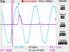
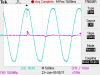
I've attached a couple of scope photos showing the surges I described. The green trace is the line voltage and the purple trace is the primary current.

Tcur1 shows the current when the grid is connected just as it crosses zero volts, increasing in the positive direction. The two very tall spikes are due to the sparking at the switch when it closes; this provides a convenient way to know when the switch closes. The current pulse doesn't happen until the sine reaches its peak. The flux in the core is proportional to the integral of the applied voltage (Faraday's law), and the core is only big enough to sustain the volt-seconds of a half sine. Under normal operation, this is just enough that the core won't saturate, since when the grid voltage gives a positive half-sine, the core is normally starting from negative saturation, not from zero flux, such as it does when the supply has been off and is then turned on.

Tcur2 shows the primary current when the secondary rectifiers are re-connected, and the grid voltage is applied at the peak of the sine. This should give the maximum possible surge due to charging the caps. You can see the dip in the line voltage where the line voltage is pulled down by the uncharged caps on the secondary. Note that the current scale is decreased to 50 amps/cm from 100 amps/cm.
 

Attachments

  • Tcur1.png
    Tcur1.png
    6.8 KB · Views: 257
  • Tcur2.png
    Tcur2.png
    6.4 KB · Views: 227
Status
Not open for further replies.

Latest threads

Back
Top