I purchased a Torin Fan Deck 240v 50hz 655W OUT--Blower from a salvage yard in near new order.
The electric motor is of four speed design Lo, Med Lo, Med High & High, It came without the speed selection switch which I don't need as I want to run it on High all the time.
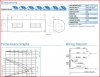
I have attached a wiring diagram of the newer 3 speed model which is 600W OUT & the same thing except 3 speed instead of 4 speed.
The high setting on mine uses the Brown wire for High so I wired the three pin mains plug accordingly & tested the blower.
It seems to labour & the speed of the motor varies & appears as if it is overloaded & gets hot.
I then dismantled the unit & checked the bearings & the stator windings etc & everything is in perfect condition so I assembled it again & run the motor with (no load) & it runs good with no variation in speed.
I assembled it into the unit with just 1 fan wheel & gave it a run & again it is good with the motor getting just warm as expected.
With the second fan wheel attached (full load) the same problem occurs, the rpm varies & the motor gets hot.
I thought that each individual stator tap was selected with the speed selection switch, so I wired the Brown wire to Active but it seems to lack the power to drive both fan wheels.
You don't have to energise all the stator taps to run on high do you, I thought they would be with just the single brown wire, the (High Setting) but maybe I am wrong?
Didn't seem correct to do this so I thought I had better ask.
Forgot to add that the mains supply is good enough for heavy welding so shouldn't be an issue.
Cheers
The electric motor is of four speed design Lo, Med Lo, Med High & High, It came without the speed selection switch which I don't need as I want to run it on High all the time.
I have attached a wiring diagram of the newer 3 speed model which is 600W OUT & the same thing except 3 speed instead of 4 speed.
The high setting on mine uses the Brown wire for High so I wired the three pin mains plug accordingly & tested the blower.
It seems to labour & the speed of the motor varies & appears as if it is overloaded & gets hot.
I then dismantled the unit & checked the bearings & the stator windings etc & everything is in perfect condition so I assembled it again & run the motor with (no load) & it runs good with no variation in speed.
I assembled it into the unit with just 1 fan wheel & gave it a run & again it is good with the motor getting just warm as expected.
With the second fan wheel attached (full load) the same problem occurs, the rpm varies & the motor gets hot.
I thought that each individual stator tap was selected with the speed selection switch, so I wired the Brown wire to Active but it seems to lack the power to drive both fan wheels.
You don't have to energise all the stator taps to run on high do you, I thought they would be with just the single brown wire, the (High Setting) but maybe I am wrong?
Didn't seem correct to do this so I thought I had better ask.
Forgot to add that the mains supply is good enough for heavy welding so shouldn't be an issue.
Cheers
Attachments
Last edited:
