Continue to Site

Welcome to our site!

Electro Tech is an online community (with over 170,000 members) who enjoy talking about and building electronic circuits, projects and gadgets. To participate you need to register. Registration is free. Click here to register now.

  • Welcome to our site! Electro Tech is an online community (with over 170,000 members) who enjoy talking about and building electronic circuits, projects and gadgets. To participate you need to register. Registration is free. Click here to register now.

To Level Translate or not to

Status
Not open for further replies.

AtomSoft

Well-Known Member
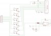
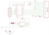
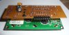
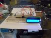
Ok im planning on using a 3.3v MCU to control a 5v Character LCD. I can supply the LCD with 5 volts no problem. But not even sure if the MCU i plan to use has 5v tolerant pins.

Can someone suggest a simple (CHEAP) way to ensure i wont damage the MCU ? Can i simply use a resistor on each pin needed?
 
I use a 5 volt Lcd with 3.3 pic the LCD works fine at 3.3 it the contrast that's the problem. so I made this just use diodes that can handle the current

hook your contrast to the - 2.4 volt end **broken link removed**

 
Last edited by a moderator:
Can i supply LCD with 5v still for power ? I plan to use the NCP1402 5v version to boost the 3.3v to 5v but will it hurt my MCU ? if the RW pin is GND and its in write mode only. I dont plan to use read mode.
 
That's not going to hurt It should work fine tie the gnds and hook the LCD to the 5 volt end. The data pins and E RS should read a high at 3.3 volts it can't make you give them more LOL.

Then I was playing with the LCD at 3.3 I found that if I raised VDD to 3.6 most where more then useable
 
Depending on which MCU you use, you can use pull-ups on a 5v tolerant, open-drain output in order to have 5v outputs from a 3.3v MCU.
 
Jason,

Just ran across these **broken link removed** (including shipping) from China. I haven't tried them yet (no money) but I suspect they might be perfect for some 3.3v projects.

Cheerful regards, Mike
 
Last edited:
Mike cool!, even tho the image shows a 5v sticker on it :)

I might just use a level translator as not to cause any damage. Would suck. I dont know which MCU i will use since this is just a main PCB. I might use it on ARM, ST, PIC not sure
 
... I dont know which MCU i will use since this is just a main PCB. I might use it on ARM, ST, PIC not sure ...

I'm in a similar situation. I've been playing with a few of the $4.30 TI LaunchPad boards which use 16 bit MSP430 micro controllers running at 3.3 to 3.6 volts. Buying a 3.3v LCD seems easier than using level conversion and dual regulators on a 5v LCD.

Good luck. Let us know what you end up doin'?

Cheerful regards, Mike
 
in fact to save money i will use transistors... 6 to be exact and simply switch the 5v.. 6 transistors cost me like $0.18 cents
might take up slightly more board space but heh .. ill use the BC846 its a General Purpose PNP... nice and cheap and simple
 
Not sure. This was going to be for sale in my store... i wanted it to be usable by any MCU...

Here is a image of my schematic ... i think it will work well. If i use a 1k resistor for the base of each and a 100 ohm i should be able to get about 20mA for each pin even tho they need like 2mA .... but it wont pull more than it needs i guess...

While it will be for sale the schematic will be OPEN SOURCE just not the PCB since i did that work really :D
 

Attachments

  • LCD.jpg
    LCD.jpg
    39.4 KB · Views: 241
Here a nice Link looks like there was a level problem using the 3.3 on some LCD have a look https://delphys.net/d.holmes/hardware/levelshift.html**broken link removed**

an ATMEL AT90S8515 (at 3.6864Mhz) controlling a Seiko L203400J000 20x4 character LCD module. The 8515 is connected to a 3V supply while the LCD requires 5V. The control lines, RS, RW and E and the data lines D0-D7 are each level-shifted with the BSS138 MOSFETs. The level-shifting imposes no directionality on the bus so both reading from and writing to the LCD are possible.
 
Last edited:
HEH COOL! Of course it would cost more to do that. Counting resistors and board space. Here is my current schematic using that IC.. i just need to order some to test it out now heh... ill get a couple DIP ... oh wait i think i have some here ! YAY!

Anyway here is the schematic:

(AS A NOTE: i dont connect the POT to VCC seems to work way better just limiting it to GND)
 

Attachments

  • LCD2.png
    LCD2.png
    12.4 KB · Views: 250
Last edited:
You have some of them cheap LCD to they work fine I like the blue I got 6 of them for $1.50 each and shipping was cheap to ended costing less then 2.50 each

O and I want my screwdriver back LOl Looks nice.
 
Last edited:
LOL on the scewdriver. These LCDs cost me $6 each lol not cheap for me. You got lucky! I just uploaded a video:

https://www.youtube.com/watch?v=buBa96gg9D0

The cool thing is i can now use this LCD on 3.3v with no problem! so i can make the PCB using a SSOP and make it smaller :) Also might make the POT SMT and on the back so you can adjust while its plugged in :)
 
Status
Not open for further replies.

Latest threads

New Articles From Microcontroller Tips

Back
Top