Continue to Site

Welcome to our site!

Electro Tech is an online community (with over 170,000 members) who enjoy talking about and building electronic circuits, projects and gadgets. To participate you need to register. Registration is free. Click here to register now.

  • Welcome to our site! Electro Tech is an online community (with over 170,000 members) who enjoy talking about and building electronic circuits, projects and gadgets. To participate you need to register. Registration is free. Click here to register now.

Time delayed buzzer that turns on when no light

Status
Not open for further replies.

modmad

New Member
hello everybody (or at least someone i hope)

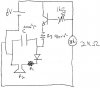
I am trying to create a circuit that turns on when there is very little light on a LDR. the resistance of the LDR when light is shining on it is 104 ohms and the resistance when there is no light on it is about 2000 ohms. The circuit that i want to turn on will just be a 9000 ohm resistor leading 2 a buzzer in parallel with a 220microF capacitor so that it will be time delayed i was using a PNP transistor (BC338) as the switch and a variable resistor to adjust the sensitivity of the switch. (i attached a basic circuit diagram of what i think it should look like).

Or at least that was the theory but i have run into a few problems firstly how do i find out what my transistors amplification is (i have no idea which of the symbols it is when i google the specifications) and secondly what would be the most effective way of making the siren turn on when its dark eg how can a reduce the current/voltage enough so that the current/voltage coming out of the transistor does not set of the buzzer.

any advice about this would be really appreciated.
 

Attachments

  • My Circuit.jpg
    My Circuit.jpg
    23.9 KB · Views: 1,084
Personally I would use a 555 for the time delay.

I don't have experience with logic gates so I may be wrong about this, but to power the timer / buzzer (or siren) circuit when the LDR's resistance is high (i.e. in darkness), you should be able to use an EX-OR gate, with one input through the LDR and the other directly from the power source; that way the output would be high when only one of the inputs is high, and since the direct supply is always high, the output would be high when the LDR conductance is low.

Again, I've never used logic gates so it may be that they only work with digital signals in which case ignore everything I just said.

EDIT: ...I also just noticed that my solution would use an EX-OR gate to do the same as a NOT gate anyway.


If I'm totally wrong about how the logic gates work could someone explain why? :) Thanks. Either way I'm sure this problem has a fairly straight-forward solution.
 
Last edited:
this link has what you want

suggestion when posting schematics, use a schematic drawing program like express pcb
LM741 Light Dark Sensor Circuit - Electronics
better op amps are available for a better acting circuit (sensitivity)
for your time delay just change the RC network attached to the transistor base.
 
Hmmm... your transistor base needs a resistor to 6V so that the voltage is divided between the resistor and your light sensor. Otherwise, you won't get a good turn on/turn off from it. Put your circuit in LTSpice, free download. Try different transistor configurations to see which works best.
 
I looked at that hand scribbling

of a schematic and have yet to figure out what I am looking at??
just go with the circuit in the lnk I posted and save yourself a few sleepless nights.
 
hey everyone thanks for your responses :)
hehe and for future reference i'll use a program to draw up the circuit lol.

the red stuff is just a long version of how i got to where i am now... probably not worth reading lol
I started doing a bit of experimenting with the circuit by putting in a resistor with the power supply like brownout said (thanks for that) and then playing with resistor values and got buzzer to turn on (i also put another resistor in parallel with collector to allow for current division and reduce amount going into buzzer) in the dark and i could also turn on the buzzer on after a time delay by using capacitor and resistor but when i tried to implement them together some funny stuff happened...

Summary:long story short the buzzer is now dead (but i got to hear some interesting noises lol)

anyways the place where i by my stuff from isn't open on weekend so i'll pick up a new one monday but till then i cant do much. i think i might pick up a 555 and the op-amp then to so i can look at using them. and maybe doing that circuit MrDEB posted (if i can work out how/why it works)

with those two things though can anyone give me a decent description of how they work or a good site about them cause i like to understand what im building :) also more a curiosity question than anything else when do u use a pnp transistor and when do u use a npn?

again thanks for the suggestions
 
oh and i tried using the logic gates but i had difficulty getting the inputs to be completely off when i wanted them to be
 
how the circuit works = follow the links in the posted link. it explains how the comparator works.
the two resistors in series w/ pot act as a voltage divider/reference
 
Status
Not open for further replies.

Latest threads

New Articles From Microcontroller Tips

Back
Top