Continue to Site

Welcome to our site!

Electro Tech is an online community (with over 170,000 members) who enjoy talking about and building electronic circuits, projects and gadgets. To participate you need to register. Registration is free. Click here to register now.

  • Welcome to our site! Electro Tech is an online community (with over 170,000 members) who enjoy talking about and building electronic circuits, projects and gadgets. To participate you need to register. Registration is free. Click here to register now.

This would be cool!

Status
Not open for further replies.

praedus

New Member
I have been searching the past 4 hours for this thing. On a some MAC computers when they are in standby they have an LED that pulsates from dim to bright. I want to make one! I just dont have any schematics. I have had some exp with breadboards and 555 timers but not to much. Thanks in advance.
 
so you mean that it doesnt simply turn on and off, it turns on and then descreases to off or it slowly turns on and then off directly?
 
Most probably they are doing it using varying PWM signal to the LED. Try searching for analog or digital PWM schematics on google.
 
Search a syrene sematic with two 555 (or one 556) it's same function: the higher frequency astable modulated by lower freq. astable multivibrator.
You can play with frequencyes to best results.
 
why not just wire 2 resistors in series with the led, adjust to give brightness desired, then add the 555 timer output pin to the junction of the 2 resistors (555 configured as an astable), as the output pin (3) goes hi and lo it shorts the lower resistor and varies the led brightness from lo to hi....... make sure you dont exceed the leds ratings or it wont last long with a "long" on time from the 555
 
Hi praedus,

here's a circuit that you need.
NOTE: the original page did not work at the time of posting so I copied all the text and the schematic here (i.e. it's not mine)


Parts:
R1,R2___________4K7 1/4W Resistors
R3_____________22K 1/4W Resistor
R4______________2M2 1/4W Resistor (See Notes)
R5_____________10K 1/4W Resistor
R6_____________47R 1/4W Resistor (See Notes)
C1_____________1µF 63V Polyester Capacitor
D1_____________5mm. Red LED (See Notes)
IC1__________LM358 Low Power Dual Op-amp
Q1___________BC337 45V 800mA NPN Transistor

Circuit operation:
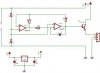
This circuit operates a LED in pulsing mode, i.e. the LED goes from off state, lights up gradually, then dims gradually, etc.
This operation mode is obtained by a triangular wave generator formed by two op-amps contained in a very cheap 8 pin DIL case IC. Q1 ensures current buffering, in order to obtain a better load drive.
R4 & C1 are the timing components: using the values shown in the parts list, the total period is about 4 seconds.

Notes:
-The most satisfying results are obtained adopting for R4 a value ranging from 220K to 4M7.
-Adopting for R4 a value below 220K, the pulsing effect will be indistinguishable from a normal blinking effect.
-The LED can be any type and color.
-You can use a filament lamp instead, provided its features are comprised in the range 3.2 to 6V, 200mA max.
-Using a lamp as a load, R6 must be omitted.
-Voltage supply range can be 4 to 6V: 4.5V is the best compromise.
-Don't supply the circuit with voltages exceeding 6V: it will work less good and Q1 could be damaged when a lamp was used as the load.
-At 6V supply, increase R6 value to 100 Ohm.
 

Attachments

  • led_pulser.GIF
    led_pulser.GIF
    2.3 KB · Views: 965
Hi all.

i'd only ask if this may work. the only diference is that i changed the NPN as i want to drive a high current (55-80 Watt at 14V) halogen bulb with this and append an voltage regulator to get the 5 volt source.

The NPN is :
TIP 142 = TIP142TU
NPN 10A/100V D TO218
 

Attachments

  • dimmer_249.jpg
    dimmer_249.jpg
    16.8 KB · Views: 647
stepping voltage down for oscillator is fine, (maybe you won't even need it, just read the datasheet for your opamp). but it is unrealistic to expect proper output from such circuit (load in emitter circuit). from circuit operating on 5V, even if opamp output would go to the positive rail, darlington would drop it some 1.2-1.5V (reqired to get base current). the output voltage (at the load) would be at best 3.5-3.7V...
 
evandude said:
I would put the load between the collector and +12, not the emitter and ground...
I might also include the emitter follower in the integrator feedback loop.
And I'm not too sure about dimming halogen lamps. I seem to recall that you can have problems if you don't do it the right way (PWM?).
 
Ron H said:
evandude said:
I would put the load between the collector and +12, not the emitter and ground...
I might also include the emitter follower in the integrator feedback loop.
And I'm not too sure about dimming halogen lamps. I seem to recall that you can have problems if you don't do it the right way (PWM?).
halogen lamps should not really be dimmed due to the re-cycling process requiring that the bulb reaches a very high temperature. If not a halogen lasts about as long as an ordinary bulb.
 
Speaking of Cool, Check out the picture I just posted here:

**broken link removed**
 
Hey Gary, if that's you then you're crazy.
That reminds me. The locals are doing their Polar Bear swim in a couple of days. I just watch because I don't want to freeze my ***** off! :lol:
 
Yes, That is Me.

Previously when I lived in Vancouver, I went for the Polar Bear Swim quite often.

But where I am now I can rarely get in as the lakes and steams here Totally Freeze Over.

Up till two days ago, we have had sub-zero temperaturers to -15 celsus for the past 3 weeks.
And yesterday it wamed up to +3, which was just enought to let me go for a swim in the creek beside my house. Not that you can see it in that picture as most of it is still really frozen, but the creek is actually about 60 feet wide.

Definately a Cool Swim, But Fun.

Merry Xmas to All.
Gary
 
Status
Not open for further replies.

Latest threads

New Articles From Microcontroller Tips

Back
Top