Continue to Site

Welcome to our site!

Electro Tech is an online community (with over 170,000 members) who enjoy talking about and building electronic circuits, projects and gadgets. To participate you need to register. Registration is free. Click here to register now.

  • Welcome to our site! Electro Tech is an online community (with over 170,000 members) who enjoy talking about and building electronic circuits, projects and gadgets. To participate you need to register. Registration is free. Click here to register now.

Theory and repair of LCD monitor?

Status
Not open for further replies.

vlad777

Member
**broken link removed**

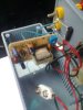
This is the power board and ccfl drive from asus vw191s LCD monitor.

On the picture is visible two ccfl transformers and on the back two
power transistors.

I'll first refresh solder on transformer pins.

People advise please.


Edit:
**broken link removed**
 
Last edited:
I have put it back together, it works but I still hear faint hissing-sparky sound.
I can't tell if it's coming from the power board.
Could it be coming from the panel?


Edit: It turned off again after 20 min.
It also happens that when I turn it on, it makes that noise and like loses vertical sync.


Edit2:

**broken link removed**

I took one ccfl off to see it and take a picture.
There are two of them in one strip.
(There are two strips, one on top and one at the bottom.)
They are very long and very thin, and apparently there is only one pin
on one side and another pin on the other side.
In the picture you can see that near the cathode/anode the glass is like burned/melted.

I put everything back, I now don't hear any noise.

Edit3:

Now it doesn't turn off.
It seems that one of the ccfls was shorting out and
it seems I have broken that very one.
Chance for that is one in four or one in two if I broke both of them.
Cheers.

Edit4:
Now I think that by breaking laps I reduced power consumption
and that now, faulty power supply can handle it.
(Yes I checked, I broke both upper lamps)
On main filter capacitor says 100uF and measures 93.3uF,
it doesn't seem to me that this is the problem.

May the force be with me.
**broken link removed**
It doesn't show because I used flashlight,
but this glow of mighty asus is blinding.
 
Last edited:
yes. sometimes if the ccfl have problems, the inverter feedback circuit can tell unit to shutdown. This can be seen on many LCD monitors when CCFL develop a slight flicker. Not all lcd have this feedback circuitry though. Also as a matter of course, check capacitors in smps with an ESR meter, if you have one. A capacitance meter wont help you here.
 
What is the tipical ESR value for a bad capacitor?

Edit:
I mentioned two transformers and transistors but I overlooked
two capacitors very near them.

After refreshing soldering, my next step should have been to change those caps
with new ones.
 
Last edited:
Depends on the cap vslue and operating voltage. Generally, any value above 5ohms is no good.

Good to see more members from South Africa joining here.

Thanks for posting

Regards,
tvtech
 
Last edited:
5 ohms is ok up to a few uF, power supply caps of 470u and larger should be ver y nearly a short, less than an ohm.
You need an esr meter not a multimeter, you can build one fairly easily, I'll send you a link if you want, they are a must for a repair techs toolbox.
If you have broken 2 of the tubes maybe the monitor is now dead, unless you have another as a donor.
 
Please send me a link or post it, I was just thinking how much would an ESR meter cost me.

Although upper lamps are broken, it is not immediately apparent when you look at the screen.
Like I said they glow pretty bright.
 
Last edited:
Thus far, I've seen 2 die of a broken screen, 5 by backlight HV inverter. One 24" broken screen TV donated its' backlight ass'y to the 24" monitor I'm on now! (major luckout)

Of 3 backlight inverters, 2 were capacitor failures alone, 1 was caps & FET drivers. All successfully fixed. One was a fractured screen And an inverter that got fixed once then died Dramatically (stunk up an office)... oh well.

If it's in the logic stages, harvest it for parts, you'll have bought it 2+ times for any fix. JMT <<<)))
 
Ok then:

https://ludens.cl/Electron/esr/esr.html

The above esr meter uses a transformer you have to wind, I'm just about to build another, the transformer came out of a scrap pc power supply, should be no beef for you, just make sure the transformer doesnt have an air gap on the centre leg, to take a tranny apart warm up the ferrite part with a hot air gun or gas solder iron with a hot air tip, they then just pull apart.
And if you really dont want to mess with a tranny try this one its as simple as it gets (translated from I think czech) some 555's need a 10nF ceramic cap from pin 5 to gnd to be stable:

https://translate.google.com/transl...ut=2&eotf=1&u=http://www.danyk.wz.cz/esr.html

The good thing with the fisrt link is that by using a transformer the test voltage is only 200mV, meaning you can test caps in circuit the test voltage is so low that semiconductors will not be biased into conduction.
 
Last edited:
Thanks. Schematics is straight forward and its easy to build accept you need to buy meter scale.
I know about that heating trick to open a ferrous core transformer, but only after destroying a few.

Czech implementation looks nasty :)
Also I notice it doesn't have what is D1 in first link?

Edit:

I suppose this ESR is only important for caps that work on high frequency,
and not important for those that work on 50 HZ like main filter cap?
 
Last edited:
vlad777;107874 I suppose this ESR is only important for caps that work on high frequency said:
Bang on the button. Mains Caps = 50 HZ @ Low Frequency smoothing. Run cool.
Secondary Caps after SMPS on Secondary outputs = High Frequency smoothing. They run hot. Lots of work to do. And dry out/up...etc. Or sometimes just visibly swell up or burst at the top. You can spot them easily if you know what you are looking for.

Main Smoothing Caps also go faulty though.....not through heat but rather things like high Mains voltage (where they visibly pop the top of the can) or simply wear out due to age and/or bad manufacturing. On a CRT TV for example, the first sign of a open MSC is a humbar that moves down the screen. And disturbs the picture. On a 220VAC input on a SMPS, you need to read around 320VDC across the MSC.

No ESR testing or anything....if you have 320VDC...your MSC is working and doing its job.

Not the most Technical explanation in the World....but a good PRACTICAL guide for basic SMPS fault finding regarding Capacitors.

Putting you on proper green vlad777

Enjoy ;)

Regards,
tvtech
 
Last edited:
Mine doesnt have a scale (just the original 'vu'), I just go off how far the meter moves if I really want to know then I'll measure a resistor and get an idea that way, if your testing you can get the feel of what sort of results you get.

Yes the czech design is a bit cheesy, however if you just wanted something to chuck in a toolbox and carry round its better than nowt, I have a few home bashed gadgets I just wouldnt have them at full price.

D1 in mine is a 1n4148, in fact they both are.
 
Last edited:
Finished my simple little ESR meter, the only thing not salvaged really is the box.

pics 002.jpg
 

Attachments

  • pics 003.jpg
    pics 003.jpg
    96.8 KB · Views: 467
The box is a PX2, I think its made by hammond, I got it from maplin electronics here in the uk, I dont shop there often, the mrs was shopping in the same centre that day.

The transformer was robbed from a pc power supply, the actual type isnt critical as long as it doesnt have an air gap.
Its very usefull for repairs as the output is only around 250mV so it doesnt make semi's conduct so you can test caps in circuit, the only time I've needed to pull them is when they are paralled up.
 
Status
Not open for further replies.

Latest threads

New Articles From Microcontroller Tips

Back
Top