Continue to Site

Welcome to our site!

Electro Tech is an online community (with over 170,000 members) who enjoy talking about and building electronic circuits, projects and gadgets. To participate you need to register. Registration is free. Click here to register now.

  • Welcome to our site! Electro Tech is an online community (with over 170,000 members) who enjoy talking about and building electronic circuits, projects and gadgets. To participate you need to register. Registration is free. Click here to register now.

Theoretical gain of common emitter amp

Status
Not open for further replies.

caffine

New Member
Hey guys

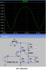
how do i calculate the theoretical gain of my common emitter amplifier

my values are as follows
VCC = 12V Beta = 239
VE = 1.2 BV = 1.9 VBE = 0.7 VE = 1.2 RE = 1200 IE = 1mA IC = 1mA
RC = 6kOhmz R1 = 148kOmhz r2 = 28.68KOhmz Re = 1.19KOhmz
C1 10.81 uF C2 = 9.99uF c3 = 93.5uF

any help provided would be aprreciated, some of these values maybe wrong im not very good with electronics hence why i am asking on here

any help provided would be greatly appreciated :)
 
Submit a schematic.
 
Your transistor probably does not have any negative feedback so it will be extremely distorted at high output levels even if it is not clipping.
If its load is 60k ohms or more then its voltage gain is about 120 but the severe distortion will make it difficult to measure.

I didn't look to see if it is properly biased.
 
It's just the usual gain equation.

[latex]Av_{CL}= \frac{Av_{OL}}{1+ \beta Av_{OL}}\\
\beta = \text{Negative feedback factor} = \frac{R_C}{R_E}\\
Av_{OL} = \text{Open loop gain, the hfe of the transistor gain}\\
Av_{CL} = \text{Closed loop gain.}
[/latex]
 
Last edited:
There are three capacitors and the one across the emitter resistor has a high value so I think there is no negative feedback. Just high gain and distortion.
 
Last edited:
Yes, it's totally open loop, the gain is equal to the hfe of the transistor.

Remove C1 and the gain will fall to about 5 and the output waveform will be less distorted.
 
Yes, it's totally open loop, the gain is equal to the hfe of the transistor.
hfe is current gain, not voltage gain.
Voltage gain is simply RC/(RE+Re) where RC is the collector load resistor in parallel with an external load.
 
Sorry, that doesn't make any sense because you haven't mentioned the curren gain of the transistor which does affect the voltage gain.
 
There are many articles that say the hfe or hFE does not affect a transistor's voltage gain.
The first article in Google is from Amature Radio magazine:
THE TRANSISTOR AS A VOLTAGE AMPLIFIER
 

Attachments

  • transistor voltage gain.PNG
    transistor voltage gain.PNG
    9.6 KB · Views: 296
I am sure your correct, but that is confusing. Is not Ie dependent on Hfe?
 
It is the angle of the slope of the base voltage to the collector voltage that shows the voltage gain of a common emitter transistor. When the hfe is high then the slope stays the same but it shifts downward. When the hfe is low then the slope stays the same but shifts upwards.
 
It is the angle of the slope of the base voltage to the collector voltage that shows the voltage gain of a common emitter transistor. When the hfe is high then the slope stays the same but it shifts downward. When the hfe is low then the slope stays the same but shifts upwards.

Are you saying Vgain has a function where m is same, something like this function.

Using slope of line equation Y=mx+b
 

Attachments

  • betashift.gif
    betashift.gif
    6.9 KB · Views: 246
Last edited:
Yes, but the curves are curved at the low current end.
A transistor without negative feedback is very distorted when it approaches cutoff.
 
There are many articles that say the hfe or hFE does not affect a transistor's voltage gain.
The first article in Google is from Amature Radio magazine:
THE TRANSISTOR AS A VOLTAGE AMPLIFIER

The author of this article makes a small error just above Figure 2. He says:

"Base current equals collector current (or emitter current) divided by Hfe and hence, with near constant voltage across the base/emitter forward biased junction, input resistance (Rb) is multiplied by Hfe. Thus we get:"

Actually, base current equals collector current divided by Hfe, or emitter current divided by (Hfe+1), but not emitter current divided by Hfe.

This means that the input resistance seen at the base of a common emitter amplifier with no (or bypassed) external emitter resistance is .026/Ie * (Hfe+1), not .026/Ie * Hfe.

So his gain expression needs to be multiplied by Hfe/(Hfe+1), and the gain of a common emitter amplifier does depend on Hfe. The dependence is slight, and becomes completely negligible for reasonably high values of Hfe, but the slight dependence is really there.
 
.... the gain of a common emitter amplifier does depend on Hfe. The dependence is slight, and becomes completely negligible for reasonably high values of Hfe, but the slight dependence is really there.
So for a calculated voltage gain of 150, it might be actually 149 or 151 depending on the hFE of the transistor and on phase of the moon.:D

I think using 5% tolerance resistors has a much greater affect on a transistor's voltage gain.
 
So for a calculated voltage gain of 150, it might be actually 149 or 151 depending on the hFE of the transistor and on phase of the moon.:D

I think using 5% tolerance resistors has a much greater affect on a transistor's voltage gain.

Exactly. This is the case for a stand-alone single common emitter stage driven by a low impedance source.

However, the author of that piece does make the point that a much greater effect is the decreased loading on a previous, moderate-to-high output impedance stage, as hfe increases.
 
The distortion from a common-emitter amplifier transistor that has no negative feedback, at a fairly high output level and driven from a low impedance source is so high that it is difficult to measure its gain:
 

Attachments

  • sim transistor distortion..PNG
    sim transistor distortion..PNG
    19.2 KB · Views: 246
Last edited:
It's not that difficult. Just reduce the input to 1 mV or less as appropriate. Such a high gain stage would only be used to amplify very small signals anyway.
 
Hey guys

can anyone give me any advice on how one would describe the functions of each component within the circuit (r1,r2,r3,re,c1,c2,c2,bc108) etc

Any help would be greatly received
 
Status
Not open for further replies.

Latest threads

New Articles From Microcontroller Tips

Back
Top