Continue to Site

Welcome to our site!

Electro Tech is an online community (with over 170,000 members) who enjoy talking about and building electronic circuits, projects and gadgets. To participate you need to register. Registration is free. Click here to register now.

  • Welcome to our site! Electro Tech is an online community (with over 170,000 members) who enjoy talking about and building electronic circuits, projects and gadgets. To participate you need to register. Registration is free. Click here to register now.

The ground terminal of a ZVS power supply ?

Status
Not open for further replies.

indula

New Member
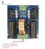
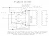
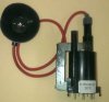
I know that the ZVS power supply produces a sine wave output due to the oscillation of capacitor and inductor circuit at the output. My question is if I want to take the zero voltage of the sine wave as a terminal where should I connect in the circuit ? Is it the middle tap wire of the coil we connect to the flybak transformer ? I have included the images please view them for further clarification of my question.
 

Attachments

  • s-l640.jpg
    s-l640.jpg
    111.9 KB · Views: 359
Here is the zvs driver circuit. The transformer is attached separately.
 

Attachments

  • images.jpg
    images.jpg
    65.2 KB · Views: 259
Is it that the transformer is not on the board?
Do these three terminals go to the transformer? If so then I think the three terminals are in red. see picture.
1572794138884.png
 
Yes, the transformer is connected separate and the 3 red circled terminals goes to the primary winding. It's a flyback transformer. the primary is woven according to the requirement and it's center tapped. The middle red circle is the center tap. What I need to know if I can use the center tap as the zero voltage compared to the other two terminals ? That means I want to take the secondary output which is also a sine output and use the center tap as the reference (zero voltage). to measure the output voltage ?

Flyback shown in image
 

Attachments

  • s-l300.jpg
    s-l300.jpg
    10.8 KB · Views: 229
Yes, the transformer is connected separate and the 3 red circled terminals goes to the primary winding. It's a flyback transformer. the primary is woven according to the requirement and it's center tapped. The middle red circle is the center tap. What I need to know if I can use the center tap as the zero voltage compared to the other two terminals ? That means I want to take the secondary output which is also a sine output and use the center tap as the reference (zero voltage). to measure the output voltage ?

No, one of the reasons for using a transformer is to provide isolation - and as in your case you're winding entirely separate coils on the core, there's no connection at all. If you want a common 'ground' then connect the ground side of the secondary winding to the negative of the primary drive circuit.
 
I think I know what you mean.
The lopty has a high voltage rectifier within, you need a voltage high enough to turn the diodes on, around 30v, you can rig something up with a led and a resistor then probe the pins to find out which.
 
What I need to know if I can use the center tap as the zero voltage compared to the other two terminals ?

Is "zero voltage" the correct term at all in this? Shouldn't it be "common" not zero voltage? The voltage is alternating between the two sides of the flyback, isn't it? Those drivers are commonly used for induction heaters that don't even connect the induction coil to that center terminal, so it isn't even needed to make the ZVS work.
 
Status
Not open for further replies.

Latest threads

New Articles From Microcontroller Tips

Back
Top