Electro Tech is an online community (with over 170,000 members) who enjoy talking about and building electronic circuits, projects and gadgets. To participate you need to register. Registration is free. Click here to register now.
Welcome to our site! Electro Tech is an online community (with over 170,000 members) who enjoy talking about and building electronic circuits, projects and gadgets. To participate you need to register. Registration is free. Click here to register now.
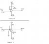
The circuit in figure 1 is a unity gain buffer, ie it has a gain of 1.
The circuit in figure 2 will not work as drawn. It needs two resistors, one between the output and inverting (-) input of the LM324, the other between the circuit input and the inverting input of the LM324.
THe circuits are also drawn unconventionally with the +ve supply at the bottom of the drawing and the -ve supply at the top. they should be the other way up.
This site uses cookies to help personalise content, tailor your experience and to keep you logged in if you register.
By continuing to use this site, you are consenting to our use of cookies.