Continue to Site

Welcome to our site!

Electro Tech is an online community (with over 170,000 members) who enjoy talking about and building electronic circuits, projects and gadgets. To participate you need to register. Registration is free. Click here to register now.

  • Welcome to our site! Electro Tech is an online community (with over 170,000 members) who enjoy talking about and building electronic circuits, projects and gadgets. To participate you need to register. Registration is free. Click here to register now.

Testing MOV's

Status
Not open for further replies.

banjomaniac

New Member
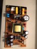
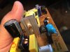
can I test MOV'S with my multi meter? I have a blu ray player power board that had a spike and trying to figure out what is at fault. Suggested by DerStrom8 to test the MOV'S but I tried in diode mode, nothing and resistance got nothing? Here is a pic of the board and I checked all the caps and the diodes too. I see 4 blue MOV'S and have desoldered one end on those. I'm getting back into electronics after a long hiatus so I've been doing a lot of reading and refreshing what little I used to know

Banjomaniac
 

Attachments

  • image.jpeg
    image.jpeg
    839.5 KB · Views: 826
MOVs should only conduct when the voltage across them exceeds the voltage they're rated for. For example if you have a 150V MOV, it will conduct only when the voltage across it exceeds 150V.

Best way to test this is to put a high-value current-limiting resistor (1M? 10M?) in series with the MOV, connect your multimeter across the MOV, and apply a voltage lower than the MOV's rating between the open leg of the resistor and the open leg of the MOV. If your multimeter shows a very low voltage even when the applied voltage is lower than its rating, then the MOV is shorted. If you apply a voltage higher than the rating and your multimeter is reading the full high voltage, then your MOV is open. To be honest I'm not sure what the failure mode generally is on MOVs, whether they fail closed or open.

This test can be a bit dangerous, so before testing make sure your connections are correct and perhaps even post images of your setup so that we can verify it is connected correctly.

Regards,
Matt
 
The 4 blue MOV's in your diagram look like capacitors Y type.
What are the numbers printed on their sides.
Appears to be a black thingy near the fuse. Either a thermistor or Mov.

A shorted MOV generally takes out the fuse, and an open one does nothing .. including no more protection.
And then there is the obvious bad state of blowing itself into nothingness except for the leads left on the board.
 
I test MOV's usually with a 15 Watt 240 Volts lamp in series, to limit the current. Put a cover over the MOV, just in case it decide to pop. Normally when a MOV has clamped a fault it is blown apart and has taken out the fuse of the appliance.
On normal 240 Volts mains voltage the lamp should not light up. I ramp the voltage up slowly to 280 Volts via a variac and step up transformer and the lamp will start to glow when the MOV starts to conduct. usually around 270 Volts mark. For 120 Volt rated MOV's I think the voltage will be around the 140 Volts mark. Put your voltmeter across the MOV to check for the clamping voltage.
 
The 4 blue MOV's in your diagram look like capacitors Y type.
What are the numbers printed on their sides.
Appears to be a black thingy near the fuse. Either a thermistor or Mov.

A shorted MOV generally takes out the fuse, and an open one does nothing .. including no more protection.
And then there is the obvious bad state of blowing itself into nothingness except for the leads left on the board.
The black part next to the fuse looks like a thermistor MF72 10D9 and and I went ahead and pulled it and measuring with my meter set on ohms it acts as a dead short, actually it is about 10k ohms so maybe it's OK? The blue ones by the fuse are SHM - X1400 Y1250 B471K F and I get a pF reading 46.5 set on the 2000pF range.
 

Attachments

  • image.jpeg
    image.jpeg
    1.7 MB · Views: 442
Last edited:
What is the voltage across the main reservoir capacitor ? (And what is you mains voltage as you give no information of your location.) Take great care measuring this as it will be a lethal voltage. Also this capacitor will remain charged for some time after the power is removed.

Les.
 
What is the voltage across the main reservoir capacitor ? (And what is you mains voltage as you give no information of your location.) Take great care measuring this as it will be a lethal voltage. Also this capacitor will remain charged for some time after the power is removed.

Les.
I measured it when I first opened this up, I get 120v AC most of the way but after the big diodes I get nothing so it's like there is no DC voltage. I need to solder back some leads and I'll check it all again.
 
Are you saying that you get 120 volts AC on the input of the bridge rectifier but nothing on the output ? As you say that the fuse did not blow then this is unususl as diode normaly fail short circuit which should have taken out the fuse. There should be about 165 volts DC across the resovoir capacitor which is normally connected directly to the output of the bridge rectifier. Can you trace out the schematic for the circuit on the input side of the transformer and put it in your next post ? I can only see two of the four diodes that would form the bridge rectifier.

Les.
I also need to know about that MOSFET? How do I know if it's good? It is a smk0460.
 
The black part next to the fuse looks like a thermistor MF72 10D9 and and I went ahead and pulled it and measuring with my meter set on ohms it acts as a dead short, actually it is about 10k ohms so maybe it's OK? The blue ones by the fuse are SHM - X1400 Y1250 B471K F and I get a pF reading 46.5 set on the 2000pF range.
Hi banjo.
Your blue ones are caps, 471K would be 470 pF.

MF72-10d9 is a NTC thermistor where the 10 is its resistance valve at room temp 25C, and D9 is the diameter of the devices element. MF72 is it's power rating. ie how much current it can handle without destruction.
It's a NTC, meaning resistance goes negative/decreases when heated.
Dead short means very low resistance(less than 1 ohm), however, you also stated 10k which means 10,000.
Please clarify. Hook up ohmeter, read value, should be 10 ohms, use solder iron tip close by to warm device for a second or so, valve should decrease.
Or even the heat from your fingers would warm it up to lower the value
 
Hi Banjo,
What evidence leads you to believe that the mosfet is the cause of the fault ? This is how I would go about testing the mosfet. I would first do some tests with relatively low voltages. Connect a 10 K resistor (The value is not critical) between source and gate. Connect the source to the negative of a DC power supply of about 24 volts. Connect the drain of the mosfet to the positive of this supply via a resistor of about 100 ohms. (At least 6 watts power rating.) Connect one multimeter set to a suitable DC volts range across the 100 ohm resistor. Connect the negative of a variable voltage DC power supply capable of giving between 0 and 10 volts output to the source of the mosfet. Connect the positive output of the variable power supply to the gate via a resistor of about 1K Connect a second multimeter between source and gate of the mosfet set to a suitable voltage range. set the output of the variable power supply to zero. Switch on both power supplies. The voltage reading across the 100 ohm resistor should be zero. Slowly increase the output from the variable supply while watching the voltage accross the 100 ohm resistor. When you start to get a reading on this meter make a note of the voltage between source and gate. This should be between 2 and 4 volts (This is the threshold voltage.) Increase the output from the variable supply to about 10 volts. The voltage across the 100 ohm resistor should be almost the full output voltage of the 24 voltage supply. If the mosfet has behaved like this it is ALMOST certainly good. It is still possible it could fail at a higher source to drain voltage. The evidence that leads you to suspect the mosfet should indicate if you need to test it at higher voltages. Another question. On your picture of the board I can't see anything that looks like a switch mode regulator chip. (Probably an 8 pin DIL package.) Is there one and if so what is the part number ?

Edit.
NOTE. Mosfets are sensitive to static damage when out of circuit so take the necessary precautions.

Les.
 
Last edited:
I have an esr meter and normally it shows transistors and mosfets as drain gate source or whatever they are but this MOSFET shows as 2 resistors? Makes no sense? There is no part with 8 pins on this board except on the back 2 surface mount parts and they are right before the output plugs that feed DC to the unit. The one that is used by the unit is STN4402 and below that its marked BD.
 
Last edited:
Hi banjo.
Your blue ones are caps, 471K would be 470 pF.

MF72-10d9 is a NTC thermistor where the 10 is its resistance valve at room temp 25C, and D9 is the diameter of the devices element. MF72 is it's power rating. ie how much current it can handle without destruction.
It's a NTC, meaning resistance goes negative/decreases when heated.
Dead short means very low resistance(less than 1 ohm), however, you also stated 10k which means 10,000.
Please clarify. Hook up ohmeter, read value, should be 10 ohms, use solder iron tip close by to warm device for a second or so, valve should decrease.
Or even the heat from your fingers would warm it up to lower the value
The veristor is indeed 10 ohms and as it gets warmer it goes down. The blue caps measure a little low BUT my capacitance meter is pretty cheesy and the caps are exactly the same when measured so I think they are fine.
 
I decided to resolder all the components I tested and start over. I started right at the AC in and then to the very next spot and so on, I have nothing at a surface mount resister labeled 105? Here is a pic link https://imgur.com/NUHl583

banjomaniac NUHl583.jpg
 
Last edited by a moderator:
You are not giving clear information. I am guessing that when you say "resistor labelled 105" you are referring to resistor R3 (Your picture is not clear enough to read the values on the resistors so I am guessing that the resistors (R1,R2,R3,R4) are labelled 105 which is the value (100K)) You also say you have nothing at this resistor but you also need to say which end of the resistor and what point it is with reference to. These resistors play no part in the functioning of the power supply. They are only to discharge the two filter capacitors so that you do not get a shock if you touch the pins on the mains plug from the charge stored in the filter capacitors.
This is how I would trace the AC trough to the rectifier. This description is from the etch side of the board. Hold the black probe on the left hand AC in pin and the red probe on the right AC in pin You should read the mains voltage (I will assume it is 120 volts.) Move the red probe to the square pad below the right AC input. The reading should be 120 volts. Move the red probe to the pad to the left that connects to the bottom of R1. The reading should still be 120 volts. Move the black probe to the top of R4 and the red probe to the bottom of R2. The reading should be 120 volts. To go further you need to say if my guess about the board layout from the component side is right or wrong. My guess is that there is a third diode to the left of the two diodes visible at the top right of the picture and there is a fourth diode at right angles to these three diodes next to the large capacitor. Also what is the part number of the 6 pin chip IC1 ?

Les.
 
Yes that is what I did, I kept the black lead on the AC line in and moved the red lead to that surface mount resistor but when I get to the other side of that resistor there is 0 volts and if there should be 120 volts on the other side of those resistors then I need to get a couple of those to try and see if that fixes it. Next question is can't I test with a regular 105 ohm resistor in place of the blown surface mount resistors just as a test?
 
Never mind, I see now that I had the wrong side of the AC line in, I'm getting voltage there. Actually I'm getting 120vAC all the way to the large yellow transformer, so maybe I need to look at the other side of that for DC voltage? sorry for the confusion so I'm going to continue on and let me get some solid data on what's what and if I find something I'll post it. Thanks for the help
 
Last edited:
I know some of you guys who are good with electronics could figure this out in no time but I'm learning. The Transformer is labeled ...
topow-1
E309025 (130B)
EF25/25 POW721

Looks like that transformer has 4 legs on Input side (side with 120vAC in) and 5 leads on the output side, how do I check for voltage and how much should there be? I'm guessing it is a reduced AC voltage?
 
I made a mistake last night (Post #15) The 105 marking on the resistors indicates 1M (Not 100K as a said last night.) I realised when I was thinking if I should have explained how to read the resistor code and convert it to a resistance value. The first two digits are a number. the third digit is the power of 10 that you multiply this number by to get the value. So 105 means 10 x 10^5 = 10 x 100000 = 1000000 One million ohms (1M) I think you should get someone with electrical knowledge to look at it as you seem to have no idea how a switch mode power supply works and you will not answer questions. The 120 volt AC mains is first rectified to about 165 volts DC on the large capacitor. The DC is then chopped by the mosfet which is driven by a switch mode regulator IC to give a high frequency (A few hundred Khz) square wave with a variable mark space ratio. this is then stepped down by the transformer and the transformer output is rectified to give the low voltage output. The output voltage is monitored and fed back to the switch mode regulator chip via an opto coupler to to control the mark space ratio of the square wave. I think you should try to learn electronics by playing with simple low voltage circuits first before attempting to fix switch mode power supplies.

Les.
 
Status
Not open for further replies.

Latest threads

New Articles From Microcontroller Tips

Back
Top