Continue to Site

Welcome to our site!

Electro Tech is an online community (with over 170,000 members) who enjoy talking about and building electronic circuits, projects and gadgets. To participate you need to register. Registration is free. Click here to register now.

  • Welcome to our site! Electro Tech is an online community (with over 170,000 members) who enjoy talking about and building electronic circuits, projects and gadgets. To participate you need to register. Registration is free. Click here to register now.

Testing a Printed circuit Board

Status
Not open for further replies.

ke1000

New Member
Hello
This my first post to the forum, to say i know nothing about electronics is to exagerate my understanding, so when my Proxxon Mill went bang and stopped working, my first thought was to hit it with a hammer, that always works doesn't it?

Sense prevailed and I have a multimeter and was hoping that there might be a logical step by step testing regime that even I might understand. I have attached 2 pics of the board, Ihope.

Any help will be much apprciated

Regards Bruce Davis
 

Attachments

  • proxxon 001.jpg
    proxxon 001.jpg
    362.1 KB · Views: 1,832
  • proxxon 002.jpg
    proxxon 002.jpg
    241.6 KB · Views: 1,799
Well the one component looks like it has a burn mark on the top of it, From here it looks like a transistor or voltage regulator, is there any part numbers on it?
 
we need to know what numbers are printed on the device which has obviously been damaged-at a guess it was either a triac or a thyristor maybe but we need the device numbers to be sure....you can set yr meter to read resistance and check for shorts on all pins on the damaged device also check each diode on the pcb for shorts too....but we do need the device part number before going any further
 
judging by a hasty schematic, the device is a Triac. basically it's a dimmer circuit feeding a bridge rectifier, which then feeds the motor.

looks like you got a metal shaving into the power supply box. most likely the triac is bad as well as the diac on the gate. the diodes in the bridge are only 1 amp diodes, this is a pretty small mill, isn't it?
 

Attachments

  • mill1.jpg
    mill1.jpg
    15.9 KB · Views: 1,695
Last edited:
Re Testing

Hello

Just got online, Wow that was quick, thanks for all the replies, I will get all the numbers off the board tomorrow.

Regards

Bruce Davis
 
Testing Board

Hello

I have tested the connections of the little cylinders on Ohms, R1 was 000, R2 was 229.9, D1 was 000, D2 was 000, D3 was 000, D4 was 000, D5 was 4.36. I hope this makes sense.

Also I have attached a drawing of the yellow side of the board, there sure is a lot of info on it. If you can't read it, I'll try again

Regards and Thanks

Bruce Davis
 

Attachments

  • PCB001.pdf
    338.7 KB · Views: 698
ok the diodes are faulty if they are reading low resistance both ways-they need to be replaced (D1-D4)replace with 1N4007,D5 may be a diac-if it is sc it needs replacing also what are the markings on tr1???
 
Hello Again

There is nothing written on TR1 that I can find, it is plastic with a piece of metal attached to it, it has 3 legs although only one seems to soldered through on the other side. It seems to be stuck to the board with resin.
D1-D4 which are black all give a zero reading even when the leads switch ends. D5 which is blue gives 4.36 one way and 9.65 the other. R1 gives zero both ways and R2 gives 229 both ways.
Sorry to be so long winded but I don't know what iis important.

Am I right in thinking that TR stands for Triac and D for Diac or diode?

Regards Bruce Davis
 
D is for diode, and TR is for transistor, and a triac is generally speaking, a transistor (actually it's the equivalent of 3 or 4 transistors). the diodes showing 0 ohms are definitely shorted. replace them with 1N4007 diodes. the diode D5 should be tested out of circuit, and should under normal circumstances read open (infinity or "OL" on a digital meter). D5 is a diac, which is a diode that acts as an open circuit until a certain breakover voltage is reached, and at that point exhibits a "snap action" and acts as a very low resistance until the current is removed or reversed. the breakover voltage is usually somewhere around 30-60V, which you won't supply from a standard ohmmeter. the triac operates on the same principle as the diac, except it can be triggered by applying a current on the gate (also known as a trigger) pin. a diac and a triac are both bidirectional devices, while an SCR acts as a triggerable one-way rectifier. diacs, triacs, and SCRs can actually be made from regular transistors, but to get all of the breakover and triggering voltages correct takes a bit of work. it's a lot simpler and cheaper to just buy the replacement parts. if you want to understand the basics of how this circuit operates, you can read here:
**broken link removed**

if you substitute a bridge rectifier and DC motor as the load, you can see how this can control the speed of your milling machine motor.

while i think of it, you might want to check your motor and make sure it wasn't burned out by applying AC across it...
 
Hello

Apologies for the delay in replying, pressure of weekend work. I have desoldered the little blue one and the reading is OL. I have checked the motor and it seems OK.
I found it very difficult to do, none of my tools were small enough to hold the blue thing, I even tried blu tack on the end of a match and my soldering iron felt enormous against the small connections. I use it for electrical work on Wiring harnesses, it's 40 watt.
Can you suggest a size of soldering iron more suited to this work and something to hold the units for when I get the black ones out.
Also where do I get the replacements from, is it RS, Maplin?

Thanks

Bruce Davis
 
a 15 or 20 watt iron should be about right. the 1N4007's can be ordered from mouser or digi-key, as can the triac.

since your device has 1 amp diodes in the bridge, a triac that will work is Q6004L4.
if you need to search for a triac, the following specs should help you find one:
600V 4A TO-220 package.

you probably should look and see if the machine also has fuses somewhere. i would expect that there are fuses, at least on the AC input.
 
well u could invest in a 25w iron and some desolder braid which you can use for parts removal from yr pcb...
 
Testing a PCB

Hello Again

I was away until Thursday, so on Friday I ordered the parts from Mouser. Will report back once I have hopefully replaced the broken ones.

Could I ask about the desolder braid, do you melt the old solder and the braid "sucks" it up?

Thanks

Bruce Davis
 
Exactly! You hold the braid to the connection, and heat up the braid and solder with the iron, and the braid wicks the solder into it.
 
Hello Again

Sorry to be a pain. but Mouser didn't have the Triac, told ne it was 9 week wait, so I cancelled the order.
My local maplin have the Diodes and a Triac that is described as Type C226M P2(case style) 600V 8A 50mA(IGT max) 30mA(IH max). They don't have a 4A one. Will this do?

Thanks for any help

Bruce Davis
 
that should work....
 
that device should be fine to use but you need to make sure the device pin outs are identical with the original device you are using as a replacement and if the device is attatched to a heatsink ,and that heatsink is earthed on the pcb you need to mount it with insulating hardware so the metal tab is isolated from the heatsink (if it is grounded at all)otherwise there may be a loud bang on switch on.......let us know how you get on
 
Last edited:
My PCB

Hello

Thanks for the replies. Last day away today, for a while. Should be able to spend some time repairing the mill from tomorrow.

Off now onto the M62

Regards

Bruce Davis
 
Repairing my PCB

Hello All

Well it couldn't go smoothly, could it? I had a nice ride to my local Maplins Friday, only to discover that contrary to what was said on the website, they didn't have the diodes or triac in stock. However they did tell me that the triac is a BTB16 600 BW. Mouser want £12 delivery for the items that cost £2 and weigh nothing, seemed a bit excessive. So I went on the Maplin site they didn't have a BTB but they had a BTA and assured me it would fit, so I ordered it, as they only charge £3 P&P.

I hope they arrive tomorrow, as I am away at Stafford from Friday.

Regards

Bruce Davis
 
re: your shop Mill PCB problem

WOW -

Had no idea you were in England of all places. I guess this site here takes posts from all the world as it were!

I couldn't help but add in some of my expert repair advice here, as I've repaired a few treadmills (TM's) in my time, and most were a bit more complicated then the SIMPLE PCB motor control you are showing in your post. I guess at roughly $1100 for that Mill you have there - the mfr in Austria wouldn't just swap out the boards huh? Guess not! Either that or it's a cheaper model with a only a few basic bells and whistles - as by the small footprint PCB design and all?

First of all - some basic sound soldering/desoldering advice is needed here.

NEVER USE copper desoldering braid if you can help it! It only helps to ruin the PCB copper runs when too much heat is constantly applied to the solder point to be worked on. Buy an inexpensive but quality type plunger desoldering tool if you can. They are under $10 and well worth the money! Practice on some bad throwaway boards first to become a desoldering Pro first, and then apply it to the good boards! You will appreciate the ease at which the solder now comes off the board, but never damages fragile PCB's. That or if you must use that copper braid then use a liquid acid flux first - on the spot to be desoldered - such as a #30 by Superior Flux & Mfg Co. Solder will now flow off the spot much quicker, and with less damaging pressure effects from the soldering iron TIP force being applied, and will also help reduce the overall heat damaging effects greatly.

Same goes for a good soldering station as well. My station of choice was/is a Weller model TC-202 (WTCPN series) base unit using a TC-201 pencil assy with Zero Tip Voltage Isolation and automatic temp controlled tip system that uses preset soldering tips according to their size (wattage or heat delivered) and use.

Even though the unit's rated output wattage might be stated at 60 watts that doesn't mean that is what is at the TIP point in so far as for heat wattage delivered. Bigger TIPS produce more wattage in the form of point area and heat. Smaller TIPS just the opposite. If I want more Tip Heat for doing bigger desoldering areas where I have to stay in contact a bit longer then I use a bigger Tip. Where delicate work is involved I use a smaller Tip.

I also don't need the fancy digital displays and extra bells and whistles with more expensive units, as I consider myself a Pro when it comes to component level repair! I learned from the BEST starting out in my Electronics Degreed field and then some!

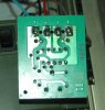
As for your posted PCB there - sure is a small control board in that shop Mill.

Most jogging/running TM's that I've worked on have 2 bigger PCB's minimum in the belt drive "motor compartment". One is the CPU Logic Brd, and the other usually being the Drive Brd. Of course you don't have a TM, so that goes without reason. Your shop Mill there looks to be a fairly simple piece of work equipment in this case.

In checking the PCB components whether they are diodes, resistors, or just basic diode junction transistors ALWAYS USE a good quality DVM to perform those tests (or a cap testing meter), and NOT by using an older analog type multi-meter - such as what I believe you are using unless I'm guessing wrong here? I just don't trust the older analog meters anymore - those that I too grew up with when I first started out eons ago now!

In troubleshooting (T/S) your (any) PCB there - always desolder only 1 lead from any axial 2-lead passive component (unless it's a multi-pin/lead passive device package then remove it entirely). Where the component IS a typical 3-pin active device transistor, SCR, TRIAC, or say (MOS)FET in nature - then definitely desolder the related part totally - even if it's heatsinked to the PCB, as otherwise you will never DVM check it out properly. Unless you definitely KNOW that the latter is true then there's no need to remove it (ie: burnt or cracked casing, etc).

I've had to do the latter with higher priced TM's even though the related Power Resistors on the PWM motor drive boards were at fault to begin with. Just because a high wattage SURGE resistor "looks good" on the outside doesn’t mean it "IS GOOD" inside. I've seen them go out of spec by as much as 50-60% of rated value and tolerance, and even partially OPEN UP when superheated - or act as an OPEN in the SURGE or feedback circuit - thus sending the control board into shutdown!!

Rarely will a 3/4 turn or single turn TRIM POT go bad unless it's a cheaply made variety to start with. I've seen the ones like you have there - on your PCB - have wiper intermittents - as from contact age, but it's rare. Always look for the obvious first!

Tapping the side of the POT slightly while measuring it should show no signs of value wander! If it jumps then its SHOT - replace it. Try and measure its "set point" out of circuit first, and replace it with a 10-turn POT instead - so a more accurate setting can be made after the R&R.

Which makes me wonder about what you said in your original post about the shop Mill making a "bang" and then it just stopped working?? That sounds more like a startup CAP blowing out - in regards to the "bang" you mentioned, unless that was indeed a purely mechanical bang you heard?

Are you sure the motor doesn't have a "soft start" CAP feature added to that drive motor mounted somewhere? Some shop routers use a "solid state" PCB soft start feature, and use a specially wound "Y" motor as well - one with a special "Y" startup winding added so that it retards a fast ramp up in speed current, but their PCB design usually has a weak IC controller chip on it - that when it fails nothing works at all. That chip being all but "proprietary" in nature is all but harder then hell to find should it (the IC chip) ever go bad - as I once found out fixing a 3hp model. I wound up just bypassing (gutting out) the controller board altogether, and just made it a single speed router. With an added $12-13 aftermarket external speed controller I bought from Harbor Freight Tools at 1/2 price on sale it worked just fine as a permanently mounted - fully speed controlled - bench router!

Anyway -

In your case - your PCB there doesn't show any outward signs of component failure at all, but to have all the bridge diodes go bad (as you say) tells me there is more going on there then just the PCB as it were. Btw - that TRIAC is just epoxyed in place so as to help prevent micro-arching should the soldered leads come loose from any excessive vibration, as I'm guessing there is when running under load. Do you have a lot of hours on the Mill? Have you also checked the DC motor brushes? Maybe the DC motor brushes are near their end life if there are high hours on the Mill? Have you ever checked them out as well?

As far as for finding electronic component parts online - I would stay away from Mouser and Digi-Key as they are a big rip off to start with - as related to their ridiculous parts price markups and all (making their real profit killing on the shipment part as you too have somewhat stated). Newark isn't too bad I would guess - although I have never had to order any electronic parts online, and then have to deal with the shipping part as well. I have tons of electronic parts outlets all around me where I live! I would maybe try NTE parts replacement if they can cross-reference that original part you have there to start with. Otherwise their direct NTE replacement part for that Q6004L4 is an NTE5645.

Hope this helps out. Let us all know OK?

Frank
 
Status
Not open for further replies.

Latest threads

New Articles From Microcontroller Tips

Back
Top