Hello,
We had a 60W offline flyback SMPS PCB layed out in an extreme rush just to get “something” ready for a customer by a certain date. (Double sided PCB)
We were then expecting the boss to allow us to re-do the PCB with a proper layout, and then test it. However, the boss then said that we must persevere with the badly layed out PCB and try and get some power out of it.
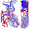
As you can see in the attached, the PCB layout is utterly diabolical.
(Red = top copper
blue = bottom copper
yellow = top silk
light blue = bottom silk)
The primary side ground is connected to pin 3 of the 16 pin pwm controller that you can see (L6566B). As you can see, there is utterly no ground plane whatsoever around this pwm controller. In fact, there is hardly any ground copper at all. In fact, the entire primary ground is a ridiculously thin trace, which goes meandering around the PCB.
The primary side ground can also be seen connecting to the large diameter , round capacitor, whose yellow silkscreen outline is visible. (round pad is primary ground, not the square one).
Anyway, despite the diabolical grounding (or lack of it), we have , sporadically managed to get some power out of this badly layed out SMPS. However, most commonly, the SMPS simply fails to start at all, or if it does manage to start, it then trips out on the L6566B’s overcurrent function (this corresponds to a current sense pin voltage of 1.5V). I don’t believe that an overcurrent actually exists, but I believe that the circuit is so noise sensitive, that the controller “thinks” that there is an overcurrent, though its actually probably just the result of severe ground bounce and general noise.
However, on a few occasions, we have indeed managed to get 20W or so out of it.
Strangely, we have only ever got it working late in the evening, never in the day time……I wonder if this is because there is simply more noisy devices running off the mains in the daytime, which is coupling noise to our poorly layed out SMPS, and preventing it from working?
Also, again strangely, we more often manage to get it working when we do NOT run it from the output of a 50Hz mains isolation transformer. Why is this? Is it because when connected to the secondary of the isolation transformer, it is floating, and not connected to ground via the neutral of our building?
Anyway, looking at the layout, are you surprised that this SMPS works at all?
(There are in fact two flybacks here, but one is just a 1W “housekeeping flyback”…incidentally, the small 1W flyback works fine)
We had a 60W offline flyback SMPS PCB layed out in an extreme rush just to get “something” ready for a customer by a certain date. (Double sided PCB)
We were then expecting the boss to allow us to re-do the PCB with a proper layout, and then test it. However, the boss then said that we must persevere with the badly layed out PCB and try and get some power out of it.
As you can see in the attached, the PCB layout is utterly diabolical.
(Red = top copper
blue = bottom copper
yellow = top silk
light blue = bottom silk)
The primary side ground is connected to pin 3 of the 16 pin pwm controller that you can see (L6566B). As you can see, there is utterly no ground plane whatsoever around this pwm controller. In fact, there is hardly any ground copper at all. In fact, the entire primary ground is a ridiculously thin trace, which goes meandering around the PCB.
The primary side ground can also be seen connecting to the large diameter , round capacitor, whose yellow silkscreen outline is visible. (round pad is primary ground, not the square one).
Anyway, despite the diabolical grounding (or lack of it), we have , sporadically managed to get some power out of this badly layed out SMPS. However, most commonly, the SMPS simply fails to start at all, or if it does manage to start, it then trips out on the L6566B’s overcurrent function (this corresponds to a current sense pin voltage of 1.5V). I don’t believe that an overcurrent actually exists, but I believe that the circuit is so noise sensitive, that the controller “thinks” that there is an overcurrent, though its actually probably just the result of severe ground bounce and general noise.
However, on a few occasions, we have indeed managed to get 20W or so out of it.
Strangely, we have only ever got it working late in the evening, never in the day time……I wonder if this is because there is simply more noisy devices running off the mains in the daytime, which is coupling noise to our poorly layed out SMPS, and preventing it from working?
Also, again strangely, we more often manage to get it working when we do NOT run it from the output of a 50Hz mains isolation transformer. Why is this? Is it because when connected to the secondary of the isolation transformer, it is floating, and not connected to ground via the neutral of our building?
Anyway, looking at the layout, are you surprised that this SMPS works at all?
(There are in fact two flybacks here, but one is just a 1W “housekeeping flyback”…incidentally, the small 1W flyback works fine)