Continue to Site

Welcome to our site!

Electro Tech is an online community (with over 170,000 members) who enjoy talking about and building electronic circuits, projects and gadgets. To participate you need to register. Registration is free. Click here to register now.

  • Welcome to our site! Electro Tech is an online community (with over 170,000 members) who enjoy talking about and building electronic circuits, projects and gadgets. To participate you need to register. Registration is free. Click here to register now.

Testing a 40673 dual gate mosfet

Status
Not open for further replies.

icom128

Member
Hi, could somebody please tell me in easy novice terms how to check a 40673 mosfet
to see if it is blown ?.

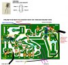
I accidentally transmitted 100w through a loop preamp , and now the preamp doesnt
work. Picture attached. Also could anyone suggest the expected parts that would have likely blown from the 100 watts transmitted through RX input part of the preamp pcb.

The preamp was built by me, as I can follow a schematic , but have no real understanding of testing the probable blown parts. I could of course build a new one entirely , but would rather know how to test probable blown parts. This preamp was a performer on a loop before my stupid error in selecting wrong antenna switch, then transmitting through the preamp.

Thanks in advance for any possible help.
 

Attachments

  • 40673 AND PREAMP PCB.jpg
    40673 AND PREAMP PCB.jpg
    284.9 KB · Views: 973
With not connections to the board and the power removed. Use your DVM in the diode check mode and measure across both sets of 1N914 diodes. It doesn't matter on the red and black leads. You should have a reading of approximately 700. That will tell you if both diode are good. A reading of near 0 means one diode or both are shorted. If you get a reading of near 0 reverse your leads and take another reading if it near 0 both diodes are shorted. If you have a reading of infinity in both directions both diodes are open.

With no connections and 12V power applied measure the voltage drop across the 100 resistor connected betwee the +12V and the output coil. Using ohms law calculate the drain current, I am thinking some where in the order of 10mA. Measure the voltage on G1 and adjust the 10K VR this volage should vary slightly. My rough calculations are that the voltage should be around 0.5V. Also check the source voltage(voltage across the 100Ω resistor) With 10mA of drain current the voltage on the source to ground I guess should be about 1V.
I hope this helps.
Ned
 
@k7elp60 I first tested a brand new 1N914 diode with DVM to diode mode , the meter black lead to cathode and red lead to anode.
I got a reading of 615 not 700 though. Then with leads reversed I got a reading of 0.

I then removed each diode from the pcb board and with DVM leads either way round the reading was 0, so I replaced all.

I then tested the 100 R resistor between + power and output coil - the 100R resistor voltage showed 0v.
So I replaced this.

I then assumed that the 40673 would also be damaged and replaced it , the preamp is now working again.
Thank you for your kind reply and expert help.
Also thank you to the other poster.

Regards
 
Last edited:
Status
Not open for further replies.

Latest threads

New Articles From Microcontroller Tips

Back
Top