Continue to Site

Welcome to our site!

Electro Tech is an online community (with over 170,000 members) who enjoy talking about and building electronic circuits, projects and gadgets. To participate you need to register. Registration is free. Click here to register now.

  • Welcome to our site! Electro Tech is an online community (with over 170,000 members) who enjoy talking about and building electronic circuits, projects and gadgets. To participate you need to register. Registration is free. Click here to register now.

Temperature measurement in LTspice

Status
Not open for further replies.
Okay I see, so in order for me to see how much power dissipation there is from the device, I need to know the thermal resistance (from data-sheets).

But if we are just going back to just measure power dissipation only in SPICE, and disregarding the temperatures.
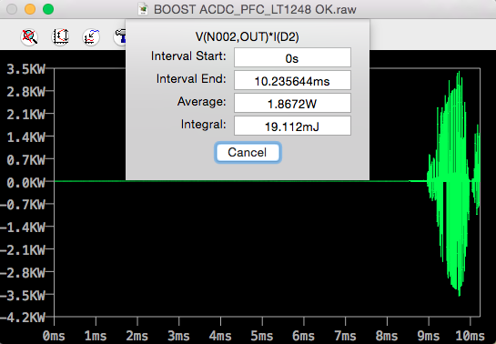
How can I measure the power dissipation in a correct way? How long time should I run the program before I can take a measurement? would 10 ms be long enough? Cause what I understand I can only measure the power dissipation in diodes and transistors only. According to ronsimpson, something is not right in the measurements, so I assuming that I doing something wrong.
I don't have time to look into this but you are not having 3k watts in D2. We are doing something wrong.
without-temp-100-png.112814
 
This is a Raspberry Pi computer that can not run SPICE. So today I can not help. Also I have much work.
D2: When conducting has 2A * 0.8V. When not conducting has almost 0A * 400V = almost 0W. There can not be 3000 watts.
Here is SPICE in my head:
1) I am concerned that both MOSFETs are turned on for 50nS and the current for that very short time is 1000(s) of amps.
2) I am concerned that the diodes have a "reverse recovery time" problem and the current is very high for 50 to 100nS.

If (1) and/or (2) is true there could be 3000 watt spikes on the silicon for <=50nS. The average watts is low but the peak is high.
 
How long time should I run the program before I can take a measurement?
If it's DC power being dissipated you only have to simulate for a short time (milliseconds or less).
If it's AC or varying with time, then you need to do the simulation over an integral number of complete cycles if you want to know the average power dissipated.
I understand I can only measure the power dissipation in diodes and transistors only.
No.
You can do any device that dissipates power, such as resistors and IC's, or even capacitors if you put the ESR value in the cap model.
According to ronsimpson, something is not right in the measurements, so I assuming that I doing something wrong.
Not necessarily.
If you do not include real world resistances in you devices, such as from a power supply or capacitor ESR, the simulation can show very high peak power, due to high current spikes.
That may not be a problem in the real circuit.
 
With a resistor you can click on it and find the V*I=W.
With a coil or capacitor the same (V*I) does not show power wasted in the part. You need to show voltage across the internal resistance of the part. I do not know how to measure wasted power in a coil or capacitor with a simple click of a button. I think you need to add an external resistor and measure its power loss. Coils and capacitors are more complex than just internal resistance but this will give a first order number.
---edited---
Adding ESR does not solve the problem. I think you must add an external resistor and measure it.
We need to be very careful what we call "measure temperature". This function has nothing to do with temperature. It is V*I of the part, which (in the case of coils and capacitors) does not equal power lost in the part.
 
Last edited:
LTspice does show the power in the internal series resistance of a capacitor or inductor, but not with good accuracy, possibly due to roundoff error in the calculation, since the peak V*I values are so much higher than the average.
This is shown for a resistor, capacitor, and inductor in series, all with a resistance of 10Ω.

upload_2018-5-12_9-13-54.png

The average power in each element is shown below.
The should all be equal but for some reason, the inductor dissipation is 10W higher.
Their sum though, is 104.5W, which is the calculated average power delivered by the V1 supply.

upload_2018-5-12_9-14-43.png
upload_2018-5-12_9-15-18.png
upload_2018-5-12_9-15-53.png

upload_2018-5-12_9-16-49.png
 
They should all be equal
Don't think so. Reactance involves phase shift, which plays a part here. If you tinker with the inductance value in the sim you can see this effect.
 
Please show your work. (post file)
How do you get this window?
upload_2018-5-12_9-14-43-png.112869
You get that window by doing a CNTL left-click on the trace name.
Don't think so. Reactance involves phase shift, which plays a part here.
No.
All resistors see the same current, so all their dissipations must be equal for equal value resistors.
 

Attachments

  • Draft52.asc
    672 bytes · Views: 80
I posted this before realising there was a Page 2 to this thread...

Run the simulation. Go into the schematic window and hold down the ALT key. Hover over the component of interest. You should find the Arrow logo has changed to a thermometer. Probe the component. This will plot the instantaneous power dissipation of that component. In the plot window, zoom into the area of interest (in the case of a power supply it is where the circuit has reached steady state). In the plot window, hold down the ALT key again and click on the plot icon. Up will pop a window showing the power dissipation of the component, averaged over that time interval. The measurement in the pop up window is the important bit - how many Watts the component is dissipating, averaged over that time interval.

LTspice will only tell you Watts of power dissipation. it will not tell you how hot the part gets. Go to the datasheet and get the Theta JA rating of the part (typically anywhere from 40 to 150 degC/W). This will give you a rough (OK very rough) guide as to how much the temperature of the part will rise as a result of the power dissipation.

Now, this is temperature *rise*, so a power dissipation of, say, 1W and a Theta JA of 50 degC/W will imply the part will rise to 50 degC ABOVE AMBIENT. If your ambient is 25 degC, the part will run at 75 degC. if your ambient is 100degC, your part will rise to 150 degC.

This is only an approximation. it depends on board layout, number of layers and what heat the surrounding components are dissipating. In fact Theta JA is so theoretical as to be almost useless in working out how hot a part gets, but the above outlines the theory.

Now for the Bramble test... wire up the circuit and power it up. If you can keep your finger on the top of the component for about 0.2 seconds, this is about 50 degC. Longer and the temperature is lower. it is difficult to keep your finger on a part that is 50 degC for more than a fraction of a second. If it hisses, it is probably above 100 degC as the moisture in your finger is boiling
 
Last edited:
All resistors see the same current, so all their dissipations must be equal for equal value resistors
You'd think so.
Modelling , say, a 100mH inductor with an intrinsic 10Ω resistance should give the same power dissipation as modelling 100mH with zero intrinsic resistance (well, 1 mΩ default is the minimum allowable in spice) in series with a discrete 10Ω resistor. Interestingly, the total power in the 1 mΩ plus the 100mH is the same, but the majority of the power is in the inductance and not the 10Ω ! Try it and see.
 
the majority of the power is in the inductance and not the 10Ω
But if the calculation is correct, the average (real) power dissipated in the inductor should be the same as a resistor with the same resistance.
The plot will show high peak values of VA, but that is reactive power, not real power.
 
You get that window by doing a CNTL left-click on the trace name.
Using your file, I can get any number from this function. (note -2.5957KW for C1) or I can get near o watts.
upload_2018-5-12_15-34-21.png

This window "average" depends greatly on when "start" and "end". By changing the frequency (159hz) by 1% changes the reading greatly. This window is reading what is on the screen. Unless the Start and End exactly match the sine wave the numbers are wrong.

Next; V(N002,N003)*I(C1) This is not power lost in the capacitor. How can we have +9kw and -9.064kw in the cap? The average might be 32 watts but the number is not right. (or not power loss)

Maybe we are "apples & oranges" again. There are a number of threads about "temperature of a part" or "power loss in a part" or "efficiency of a PWM". Using LTSPICE I can make a circuit that will have a negative 9kW in a capacitor. This should cause it to freeze in 10uS. In the same way a positive 9kw will cause the cap to explode in 10uS.
Again V*I(C) does not get us power loss.
 
This window "average" depends greatly on when "start" and "end".
Of course. That's how "average" works.
V(N002,N003)*I(C1) This is not power lost in the capacitor.
Nope. Never said it was.
That's the apparent power (V*I).
But if you do the average of V*I over an integral number of cycles, you get the average (real) power.
 
Hmm, but when I try to get the power dissipation from my capacitor C13. I got 143 W? Its too high I think? Or what do you think?
Maybe I do something wrong, I tried to follow your advice here. and I put an serie resistance of 10m ohm in C13 as well. Could you please help me crutschow? :)
 

Attachments

  • BOOST ACDC_PFC_LT1248 OK.asc
    6 KB · Views: 62
  • powerlosses.png
    powerlosses.png
    67.4 KB · Views: 65
Last edited:
And how do check the power dissipation here for DC/DC converter? I don't get it why the losses are too small (only 0.628 W)..compared to the hand calculated values, the losses should be like 10 W or something for each component...
 

Attachments

  • OFF_FULL_DCDC OK.asc
    4.2 KB · Views: 63
My faith in Spice's power calculations is being tested :D.
It seems your circuit can achieve over-unity!! If you set the sim period to 10mS and start saving data at 2mS, then over the 8mS interval the average 'power' provided by V1 is ~791.9W but the average power dissipated in R1 is 795.7W :confused:.
[Explainable by the load seen by V1 being primarily inductive]
 
Last edited:
But it should't be inductive load, the load should be more resistive due to the PFC function :/ I think I can't improve that circuit anymore?

--edit--

I can't believe that it would be so hard to obtain the power losses/dissipation...
I think it is way too high, I have input current of 8 A, and this gives a huge average power dissipation at DC-link: 437W over a time of 40ms.
This can not be reasonable ..

--edit--
I really need help with this, I have a deadline soon, where I need to present my power losses..
 

Attachments

  • powerlosses C.png
    powerlosses C.png
    66.1 KB · Views: 70
Last edited:
Nope. Never said it was.
That's the apparent power (V*I).
But if you do the average of V*I over an integral number of cycles, you get the average (real) power.
Aha, so If I divide ENERGY (J) with number of cycles (in this case T=40ms) I will get the power losses for the capacitor? Like this equation shows below?
 

Attachments

  • question.png
    question.png
    26.1 KB · Views: 183
Last edited:
Status
Not open for further replies.

New Articles From Microcontroller Tips

Back
Top