Continue to Site

Welcome to our site!

Electro Tech is an online community (with over 170,000 members) who enjoy talking about and building electronic circuits, projects and gadgets. To participate you need to register. Registration is free. Click here to register now.

  • Welcome to our site! Electro Tech is an online community (with over 170,000 members) who enjoy talking about and building electronic circuits, projects and gadgets. To participate you need to register. Registration is free. Click here to register now.

temperature control design

Status
Not open for further replies.

Napst3r

New Member
hi everybody i need to design a temperature control unit that works in acordance to light, ie: when there is minimal light then the heating element must come on, and when there is lots of light the heating element must go off...


these are the following specs of the design:
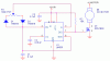
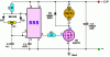
-555 timer must be used
-heating element is a 12VDC lamp (60W)
-max heat at 3cm away must 40 degrees celcius
-12VDC supply
-controlled voltage (dc chopped voltage)
-LDR
-LED's for status indications
-when the max temp is reached the circuit must switch off...

any advice and design suggestions are more than welcome
thanks alot
Lance
 
Would this be some sort of homework assignment?

As to using the 555 as a photocell detector (light/dark) with LED status inducators this link should serve as a start. What additional parts can be used? How do you plan to sense temperature? Temperatuire sensing I would think about a thermistor in conjunction with a comparator. A 60 Watt 12 VDC lamp is a 5 amp load so you will need to drive the lamp with a relay or MOSFET. You haven't provided much information as to this project.

Ron
 
okay thats at least a start thank you very much !!
let me try and be a bit more specific,

this is quoted from my study guide:
you are required to design a temperature control unit that has to perform the following:
-the temp is to be controlled as a function of light intensity, this means the darker it gets the more heat must be generated.
-in order to conserve energy, the part of the system that heats up must have the highest possible efficiency.
-a user interface must inform the user of all operational statuses (eg indicator for heting element on/off)

Design constraints:
- to meet the requirement of high efficiency heating, the heating element must be supplied with dc chopping for this a 555 timer is needed
- the heating element is a 12VDC lamp (type of car lamp) which provides good infra red radiation as a heat source
-power supply of 12VDC

design and contruction:
-heating element to be controlled (60W)
-max temp at 3cm away must be 40 degrees celcius
-controlled voltage
-light sensor LDR or a phototransitor.

and that is about the best contraints that we have, everything else is to your descretion,
so any other components can be used, but also within reason
 
Can you even get 40C with a 12V lamp? I would start with a thermo analysis to see if it can be done. Maybe you'll need more than one lamp. You'll also need a temperature sensor, a NPT thermister perhaps, and a comparator for determining when the temperature has reached the target. I guess the compare voltage can change in proportion to the light sensor. This shouldn't be too hard to do.
 
Last edited:
Can you even get 40C with a 12V lamp? I would start with a thermo analysis to see if it can be done. Maybe you'll need more than one lamp. You'll also need a temperature sensor, a NPT thermister perhaps, and a comparator for determining when the temperature has reached the target. I guess the compare voltage can change in proportion to the light sensor. This shouldn't be too hard to do.

Good question, beats me. They want 40 degrees C. (104 degrees F.) which isn't that warm. They mention 12 volt automotive bulb and 60 watts in the mix. I am guessing they want to maintain a temperature of 40 C. at a distance of about 3 cm or 1.2 inches from the bulb. They want to control the temperature using chopped DC (I assume maybe PWM) and a 555 figures into things.

I would likely start with a 12 volt halogen bulb (maybe a headlamp bulb) that is about a 60 watt bulb. Figure that bulb will draw about 5 amps. Using a temperature probe (sensor) I would do as BrownOut suggest and see if at a distance of 3 cm with the bulb at full intensity you can get 40 C. This does not take into consideration like room temperature or other variables.

Assuming you can exceed 40 C. I would think about using a LDR to sense the light and configure the LDR into a circuit using a 555 with PWM. Similar to one of the attached images, maybe a scheme like that? The 50K pot being replaced by the LDR and another pot in the scheme? I am guessing here. The MOSFET actually used would need to drive the load so needs to handle maybe 7 to 10 amps for a comfort zone? The LDR would need to be shielded to see only the heat source bulb.

I don't know but that would be a very, very rough guess. :)

Ron
 

Attachments

  • 555 PWM Circuit.gif
    555 PWM Circuit.gif
    6 KB · Views: 365
  • 555 PWM Dimmer 12V.gif
    555 PWM Dimmer 12V.gif
    4.9 KB · Views: 324
Last edited:
Reloadron, you forgot the attached image.

Nevermind, I guess you meant on an earlier post.
 
Last edited:
No, I screwed it up and added them. Damn, you were quick. :)

Ron
 
Status
Not open for further replies.

Latest threads

New Articles From Microcontroller Tips

Back
Top