Design Formulas Simplify Classic V/I Converter
Ok, I found a good article on the web that shows a simple circuit and associated formulas for converting a voltage level signal to a 4-20 mA current loop. You have to scroll down to the second article on the PDF. Study it, and I think you can design a transmitter to do what you want.
I see that you will be having two instruments in the loop that add a total of 1kohm resistance to the loop. Please go into detail as to what these instruments are, because you said they get power from the current loop. (If they are analog style panel meters, or chart recorders or something else) I don't see a problem with that per/se , but if they add resistance to the loop, I think you have to take that into account and nulify it with a calibration circuit. I have professional training with transducer transmitters, proccess instrumentation, and proportional controllers, but since I work in a lab and not the field, I have forgotten a lot, and I never designed transmitters or controllers, just calibrated or repaired them. So, in other words, the best I can do is point you in this direction with this article, and maybe answer any question that might come up.
I still manage to stick my foot in my mouth occasionally
Don't worry, we all do! I like to feel like I know a lot about electronics in general, but a wise man knows what he doesn't know as well as what he does. MSTECHCA just obviously has never heard of control loops, and that stands to reason if he never worked in an industrial setting. That is OK, because I know very little about programming uControllers, but I won't be adding my 2 cents on that subject very often!
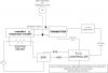
This might be a little oversimplified but I drew this: