Hello,
I have a Chinese made PC power supply that I would have liked to use for an electronic (3d printer) project. I just need to use the 12V.
The unit presents it self with the following problem:
Unloaded voltage: 11.16V
Load of ~0.7A (big fan): 10.73 V
Load of ~3A (heating cartridge): 9V
Load of maybe some 8A (heatbed): PSU shuts down
So I open up the thing and start probing.
I identify the following:
A LM339N chip compared the output voltage with the reference and sends a signal to what I believe is an TL594 chip (number scratched out, but matches the pins and the numbers that is readable). This one is in push-pull mode and it sends a PWM signal to two transistors who uses a small transformer as insulation and then it makes the charge/discharge on the big transformer.
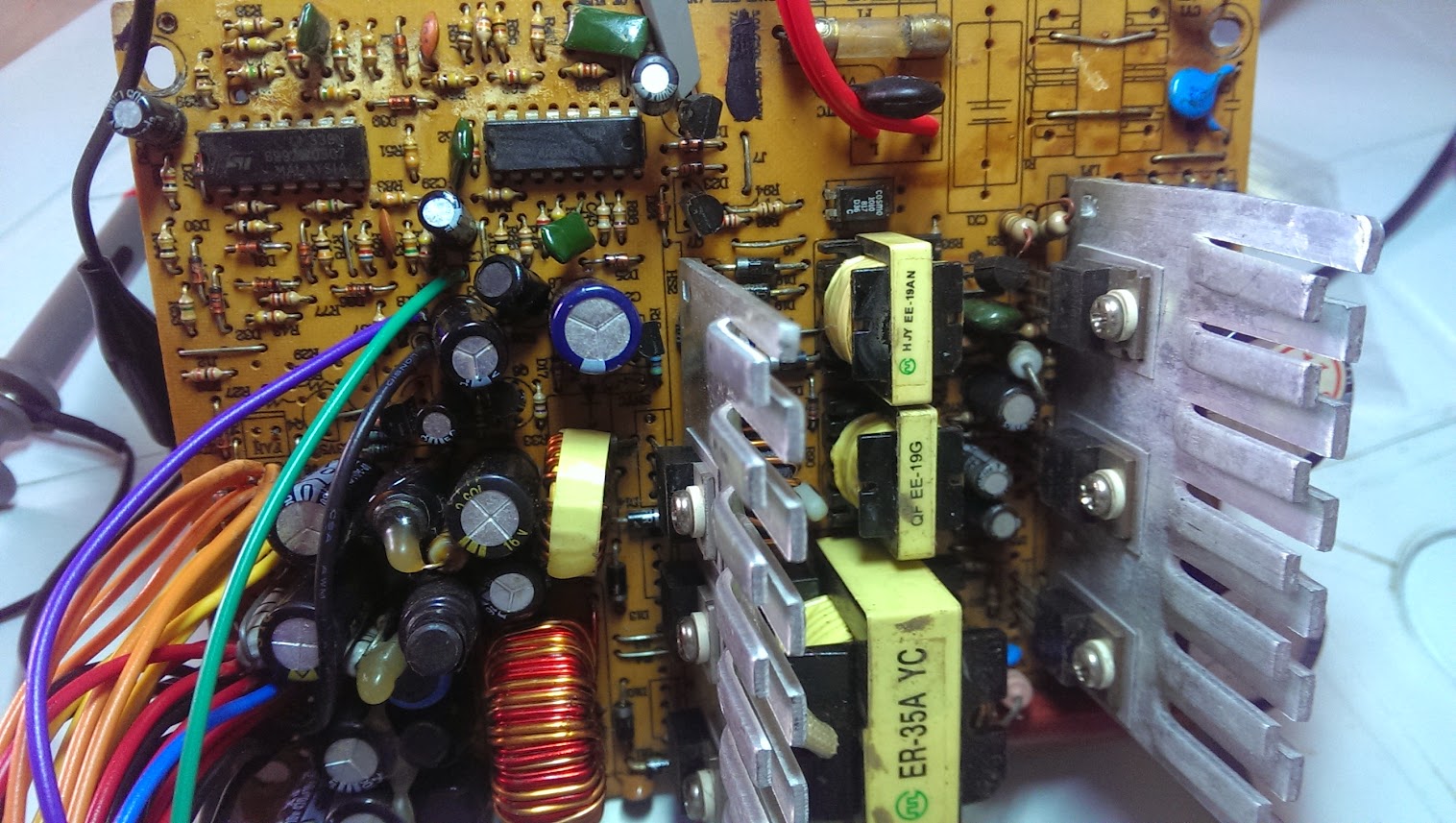
The system also as an Optocopler (next to the yellow transformer). I do not know what this one does as there are no PWM pulse on it and it is just sending a fixed voltage independent of load.
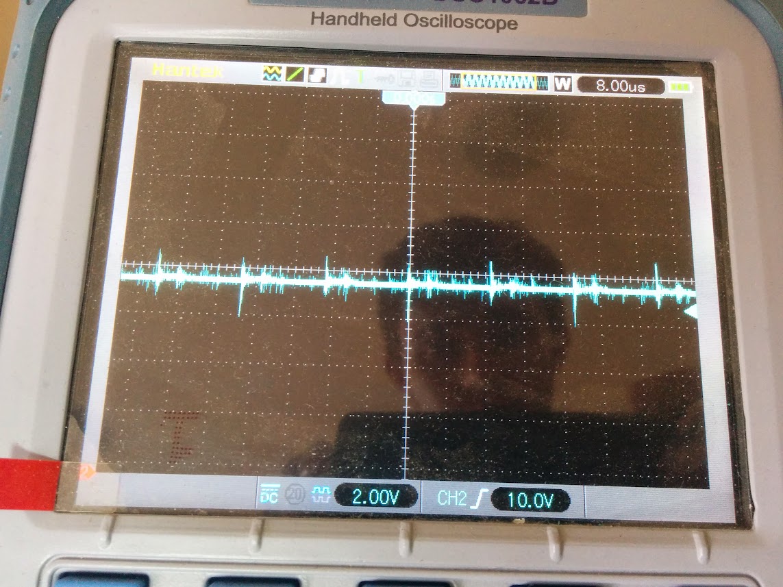
I have looked at the following:

Unloaded voltage with small transients of some 1V.
With 0.7A load.
Also my DMM does not see AC current (I read that 0.5VAC on output read by DMM is an indicator of bad filter caps)
I then check the big transformer to see the wave form:
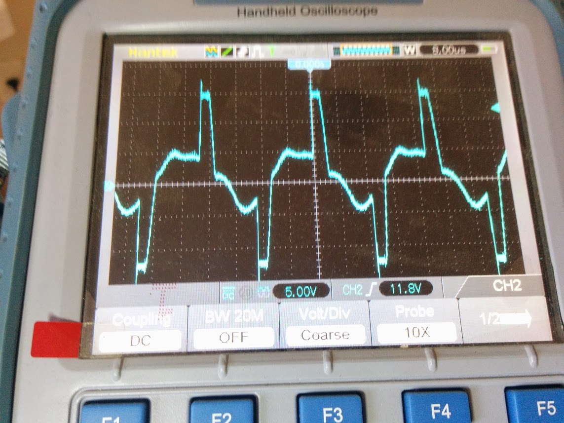
Unloaded.

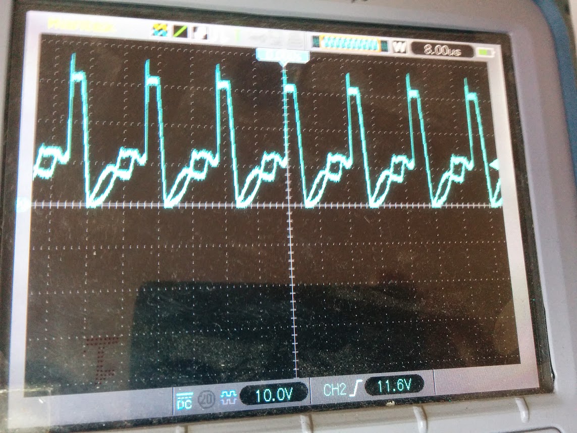
Loaded.
Clearly it is changing the PWM signal accordingly to load. This is also what I see when measuring on the IC's and they pump the transistors and all.
And finally the 12V rectifying diode (output):
Unloaded
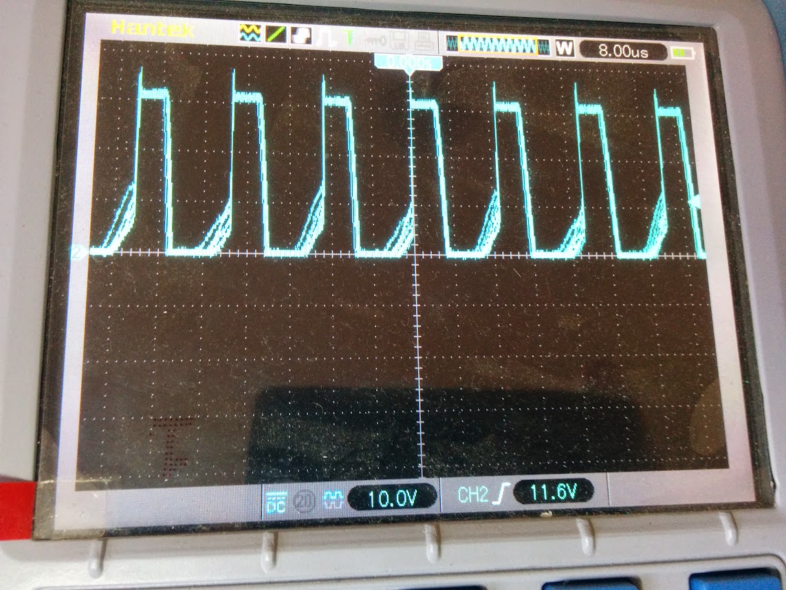
Loaded.
Also there is no obviously bad caps and no burned components. But the board really looks like a disasters soldered underneath and also on top it does not look the best.
The fuse has been all-right all along.
I am powered by 110V and 60Hz.
The unit does not get hot anywhere.
This is my 2nd "real" try at repairing "advanced" electronics and electronics is not my profession (else I played some with Arduino etc). My first repair (a battery charger for the Dremel) I changed the bad capacitors and saw green diode light and was thinking all is good - Soon after it burned so many parts that repair is now hopeless and it also fried the Dremel battery - What I want to say with that, is that I am new in this and "you probably already tried so I wont mention that to him" does not apply for me. If you think of something even basic don't hesitate to let me know.
Thank you,
I have a Chinese made PC power supply that I would have liked to use for an electronic (3d printer) project. I just need to use the 12V.
The unit presents it self with the following problem:
Unloaded voltage: 11.16V
Load of ~0.7A (big fan): 10.73 V
Load of ~3A (heating cartridge): 9V
Load of maybe some 8A (heatbed): PSU shuts down
So I open up the thing and start probing.
I identify the following:
A LM339N chip compared the output voltage with the reference and sends a signal to what I believe is an TL594 chip (number scratched out, but matches the pins and the numbers that is readable). This one is in push-pull mode and it sends a PWM signal to two transistors who uses a small transformer as insulation and then it makes the charge/discharge on the big transformer.
The system also as an Optocopler (next to the yellow transformer). I do not know what this one does as there are no PWM pulse on it and it is just sending a fixed voltage independent of load.
I have looked at the following:
Unloaded voltage with small transients of some 1V.
With 0.7A load.
Also my DMM does not see AC current (I read that 0.5VAC on output read by DMM is an indicator of bad filter caps)
I then check the big transformer to see the wave form:
Unloaded.
Loaded.
Clearly it is changing the PWM signal accordingly to load. This is also what I see when measuring on the IC's and they pump the transistors and all.
And finally the 12V rectifying diode (output):
Unloaded
Loaded.
Also there is no obviously bad caps and no burned components. But the board really looks like a disasters soldered underneath and also on top it does not look the best.
The fuse has been all-right all along.
I am powered by 110V and 60Hz.
The unit does not get hot anywhere.
This is my 2nd "real" try at repairing "advanced" electronics and electronics is not my profession (else I played some with Arduino etc). My first repair (a battery charger for the Dremel) I changed the bad capacitors and saw green diode light and was thinking all is good - Soon after it burned so many parts that repair is now hopeless and it also fried the Dremel battery - What I want to say with that, is that I am new in this and "you probably already tried so I wont mention that to him" does not apply for me. If you think of something even basic don't hesitate to let me know.
Thank you,


