Continue to Site

Welcome to our site!

Electro Tech is an online community (with over 170,000 members) who enjoy talking about and building electronic circuits, projects and gadgets. To participate you need to register. Registration is free. Click here to register now.

  • Welcome to our site! Electro Tech is an online community (with over 170,000 members) who enjoy talking about and building electronic circuits, projects and gadgets. To participate you need to register. Registration is free. Click here to register now.

Tank Control

Status
Not open for further replies.

david_mora

New Member
Hi people, I'm relatively new in industry, so i need some help. I'm designing a control system for a tank. The kind of control is "latch - unlatch", so I need a MAX and a min value of hight. The problem is the tank is underground and it is not accesible, so I thought about 2 proximity sensors IP68 (waterproof) but i'm not sure about this, and the other alternative is to use a ultrasonic sensor and a comparator (PIC16F877).
What should I do????
I'll be thankful for yor help.
 
What's in the tank? What is the application? If this isn't for a personal project, there exists already plenty of commercial and industrial solutions.

j.
 
tanke control

well it is a simple tank control, it contents commercial water and there is no turbulence. After investigating a littele more about sensors, I've found 3 alternatives:
-01 Ultrasonic Transmitter with 2 switching points
-02 Proximity Sensors (capacitive) with relay output and IP68.
-02 switching floaters.

The problem is that we have now installed a system consisting of 02 switching floarters, but the bad thing is that we have to do maintenance work every 2 months, and that means to cut the water supply in different areas of the complex. The principal thing on this is that the sensor must require minimum maintenance, once a year as maximum.
Thanks a lot for the peolple who answer my previous letter.
 
Re: tanke control

david_mora said:
well it is a simple tank control, it contents commercial water and there is no turbulence. After investigating a littele more about sensors, I've found 3 alternatives:
-01 Ultrasonic Transmitter with 2 switching points
-02 Proximity Sensors (capacitive) with relay output and IP68.
-02 switching floaters.

The problem is that we have now installed a system consisting of 02 switching floarters, but the bad thing is that we have to do maintenance work every 2 months, and that means to cut the water supply in different areas of the complex. The principal thing on this is that the sensor must require minimum maintenance, once a year as maximum.
Thanks a lot for the peolple who answer my previous letter.

Clean water, use 3 stainless steel rods and pass a vey low current though the water to determine the level. This will never require maintenance.
 
thank you very mauch for your help, but i still have doubts, can you explain me a little more about the 3 stainless steel rods and the very low current???
 
Parallax

Check out the education material at the Parallax stamp site. They have a tutorial/details on a capacitance measuring system for water. Check out the "applied sensors" book, it's free.

**broken link removed**

Also check column 27 here:

**broken link removed**

You can implement all this with a pic as well.

Resc.
 
thans very much for your help
 
david_mora said:
thank you very mauch for your help, but i still have doubts, can you explain me a little more about the 3 stainless steel rods and the very low current???

Normal water conducts electricity - distilled water doesn't (or at least not very much). By having three stainless steel rods of different lengths in the tank, one down towards the bottom (A) (always in the water), one on the minimum mark (B), and one on the maximum mark (C). By measuring the resistance between A and the other two you can determine maximum and minimum settings.

So if you test A-B, and it doesn't read, you know the tank is below minimum, if it does read you know it's above minimum.

If you test A-C, and it doesn't read you know it's below maximum, if it does read the maximum level has been reached.

Stainless steel rods are adviseable as they don't corrode (avoiding maintenance), and low currents to avoid electrolysis. Although, to be honest, you wouldn't be pushing high currents through water anyway. It's probably a good idea to measure using an AC, rather than DC, voltage - although this possibly wouldn't be needed with stainless steel.

Try using your multimeter to measure the resistance in the water, see what it reads - depending on it's purity, and the distance between the probes, probably 100k's or 1M's.
 
Hi David,

There are many commercial units available made exactly for this job.
Most of them involve the vertical movement of the air-to-water
interface at the surface of the water in the tank to register level.
This range includes those units which rely on things that float,
and units which rely on things that bounce echoes,
and units which rely on conduction sensors that make contact with
the water itself.

All of these types which involve surface interaction have their own
problems ranging from pivots that sieze, floats that leak, cobwebs
that echo, damp that attacks electrics, corrosion that can wreck
electronics, insects that set up home in electrical units. Problems
too numerous to list, most of which can be overcome by frequent
maintainence.

The most reliable arrangement that i have met for this job where an
underground tank is involved, is the simple bubbler pressure sensor.

With this type of unit all the electrics and sensing gear is above
ground, and can be easily accessible if necessary.

The piece that goes into the water is just a length of tubing with an
open end. Probably tied to a stone to ensure it stays at the bottom.

Tubing probably plastic so that it wont corrode. Weight probably a
stone or a brick so that it wont corrode. Tied with maybe itself or
plastic string so that it wont corrode.

This is the most reliable and maintainence free arrangement i have
ever seen on this type of job. Just keep the air flow pretty low,
just enough for about a bubble per second roughly, as i have known
one which was set too high had a build up of grime and dust due to
the air flow. It did not stop it working, but it got a bit messy.
after cleaning and adjusting the air flow down to a sensible low flow
it was fine and stayed clean. I think faster moving air seems to stir
up dust and carry it about.

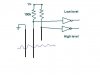
The associated electrics for this type of arrangement is very simple
generally a diaphragm is used to operate switches at the pressures
corresponding to the 'Hi' and the 'Lo' levels.
If an 'all-electronic' arrangement is wanted, there are pressure units
that can be used with electronics instead of diaphragms.

Fish-tank type pumps are cheap and very reliable, and count typical
running time in months or years.

Best of luck with your project, John :)
 
david_mora said:
thank you very mauch for your help, but i still have doubts, can you explain me a little more about the 3 stainless steel rods and the very low current???


Nigel sums it up nicely.

I have used this method for pump controllers to pump in and out mostly for building sump pits and booster pumps for domestic water tanks.

The only draw back with this method is that a some flotsam like a plastic bag or dead pigeon could get caught up in the probes causing it to miss read.

With float switches they have to remain water tight along with the cables also you have to make sure they do not get tangled or caught on something. You dont have this problem with these probes, no moving parts and nothing to be kept dry.

Here is a very rough circuit to give you the idea. With the ones I have installed I put diodes and caps to protect the inputs in case some idiot goes wild with an arc wielder inside the tank.
 

Attachments

  • water.jpg
    water.jpg
    12.4 KB · Views: 553
thnaks everyone for your help
 
Status
Not open for further replies.

Latest threads

New Articles From Microcontroller Tips

Back
Top