Continue to Site

Welcome to our site!

Electro Tech is an online community (with over 170,000 members) who enjoy talking about and building electronic circuits, projects and gadgets. To participate you need to register. Registration is free. Click here to register now.

  • Welcome to our site! Electro Tech is an online community (with over 170,000 members) who enjoy talking about and building electronic circuits, projects and gadgets. To participate you need to register. Registration is free. Click here to register now.

Take a look at these Preamplifiers please

Status
Not open for further replies.

Electronman

New Member
Hello,
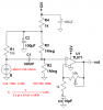
Several days ago Ron and audioguru suggest me the below electret mic amplifier.
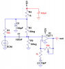
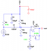
I have used to change the values and see the results so the second pic with green marks is my modification.
I operated the circuit with a 9V battery and used a headset at its output.
The result after modification was very amazing.
The mic can detect every small noise. I was so amazed when I operated it. I could hear my heartbeat too.

Now does everybody have any idea if I can make this circuit more sensitive somehow? Maybe I use it as a directional espionage microphone (Sorry do not know what do you call them)?

Besides, I have a satellite dish (the radius is 90cm), do you guys know how many distant I can detect with it?

How many distant the commercial ones can detct?

Thanks.
 

Attachments

  • auigruo.PNG
    auigruo.PNG
    11.5 KB · Views: 204
  • my modification.PNG
    my modification.PNG
    10.8 KB · Views: 187
The circuits you've posted look fine.

Good luck finding a 440k pot or a 64k resistor though.

You'll find a 500k pot and 68k resistor much easier to get hold of.
 
The circuits you've posted look fine.

Good luck finding a 440k pot or a 64k resistor though.

You'll find a 500k pot and 68k resistor much easier to get hold of.

Sorry I have used a 500k pot but the 440k is what I measured at its ends!

The same for the resistor, it was a 67k and I measured 64k at its ends.
 
Besides, I have a satellite dish (the radius is 90cm), do you guys know how many distant I can detect with it?

How many distant the commercial ones can detct?
The TV crews at U.S. football games use a parabolic dish about that size with a mike at its focus to listen to what the players are saying on the field, probably 25-50 yards away. So I would expect you might be able to hear normal conversation that far.
 
The same for the resistor, it was a 67k and I measured 64k at its ends.
I doubt it was 67k - that's not a standard value.
Are you sure it's not 62k?
 
The TV crews at U.S. football games use a parabolic dish about that size with a mike at its focus to listen to what the players are saying on the field, probably 25-50 yards away. So I would expect you might be able to hear normal conversation that far.


Well I made a test with my above circuit and a 90cm dish. The result was not promising?!
I expected a much better result anyway.

The bellow shows a parabolic mic for selling. It uses just 2 batteries and a dish that is smaller than mine, but it covers 300 yards!!!

I am wondering what kind of circuits and mic it does use?
**broken link removed**
 
Did you move your mic around? Parabolic dishes have a VERY small sweet spot you have to get the mic, and the shape is very important.

The link you posted is broken.
 
Did you move your mic around? Parabolic dishes have a VERY small sweet spot you have to get the mic, and the shape is very important.
.
The mic should be located very close to where the original satellite LNA was located.
 
A TL071 with a closed loop gain of 4400 (Gain=Rf/Rs + 1)will have a bandwidth of about 700Hz. Not too good if you want to listen to voices. That's why I limited the AC gain of the modulator circuit I gave you to about 150, so you would have 20kHz bandwidth.

The reason for this is that feedback amplifiers have a property called gain-bandwidth product. On the TL071, it is 3MHz.

Code:
Gain   Bandwidth
   1     3MHz
  10     300kHz
  100    30kHz
  1000    3kHz
etc.
 
Last edited:
Did you move your mic around? Parabolic dishes have a VERY small sweet spot you have to get the mic, and the shape is very important.

The link you posted is broken.

No, I just removed the LNB and put the mic instead.

The link does work for me?! please check the first result in the bellow:
pro dish D-EAR - Google Search

Can somebody tell me if there is a such device (check the bellow link for it):
https://saintview.wordpress.com/2009/02/22/gadget-for-hearing-sounds/
 
Last edited:
A TL071 with a closed loop gain of 4400 (Gain=Rf/Rs + 1)will have a bandwidth of about 700Hz. Not too good if you want to listen to voices. That's why I limited the AC gain of the modulator circuit I gave you to about 150, so you would have 20kHz bandwidth.

The reason for this is that feedback amplifiers have a property called gain-bandwidth product. On the TL071, it is 3MHz.

Code:
Gain   Bandwidth
   1     3MHz
  10     300kHz
  100    30kHz
  1000    3kHz
etc.

Oh, Thanks for reminding.
Ron I can calculate the bandwidth of an opamp at a certain freq or I can find it at the Datasheet?

So th solution is using an opamp with a higher bandwidth right?
Do you know any? I want to provide several op-amps for my workbench, I will be glad if you and or audioguru give me several numbers for high bandwidth and good opamps.
 
I found LM833 and LM318 have a gain bandwidth product equal to 15Mhz So Can I use them for the above circuit and have a more sensetive circuits by changing the resistors?
Is that the mystery of the above circuit or I have to find another more sensetive mic (I do not know I f there is any?).
 
A good audio opamp (OPA134) has a bandwidth of 30kHz when its gain is 300 which is plenty of gain for a microphone.
If the gain is higher then the acoustical and electrical noise will be too high.
 
Can you please tell me hoe to calculate the input and the output capacitor values please?
What thing does affect the values?

Thanks
 
The value of the capacitor and the impedance it is fed from or the impedance that it feeds determines the low cutoff frequency.

The calculation is simply: 1 divided by 2 pi RC and the answer is the -3dB frequency in Hertz.
 
Last edited:
The value of the capacitor and the impedance it is fed from or the impedance that it feeds determines the low cutoff frequency.

The calculation is simply: 1 divided by 2 pi RC and the answer is the -3dB frequency in Hertz.

Sorry I am a newbie in the electronics filed.
Can you tell m what is the cutoff freq fror the audio which is sent to the opamp via the mike?
The answer is in hertz but you told about dB:confused:?

the R in the formula is the input resistor? How can I calculate it? I do not see any resistor in series with the C1 in your circuit??
 
The electret mic is about 3.3k ohms and is in series with the 10k resistor that powers it.
The bias resistors for the opamp input are in parallel with a total of 500k ohms.
The 100nF capacitor creates a -3dB response at 3.4Hz. -3dB is half the power or 0.707 times the output level and is barely noticeable as a small loss of level.

The 10uF capacitor and the 1k resistor also create a loss of -3db but at 16Hz.

the output capacitor creates another -3dB loss at the frequency where its value combines with its load resistance.

The total of the three RC highpass filters causes the response to be -9dB which is quite a lot of loss. The response of the entire circuit is flat down to about 60Hz.
 

Attachments

  • electret mic preamp.PNG
    electret mic preamp.PNG
    12.7 KB · Views: 181
Status
Not open for further replies.

Latest threads

New Articles From Microcontroller Tips

Back
Top