Continue to Site

Welcome to our site!

Electro Tech is an online community (with over 170,000 members) who enjoy talking about and building electronic circuits, projects and gadgets. To participate you need to register. Registration is free. Click here to register now.

  • Welcome to our site! Electro Tech is an online community (with over 170,000 members) who enjoy talking about and building electronic circuits, projects and gadgets. To participate you need to register. Registration is free. Click here to register now.

Switching regulator

Status
Not open for further replies.

bhargavprasad

New Member
hi,
I am doing a project on power supply design. my input is 12v,1amp. my required outputs are 7v,400mA; 3.3v,500mA; 1.8v,600mA.
help me in selecting the corrrect topology.
i have a quest..
why is a inductor used in switching regulator?:confused:
 
Converters that increase the voltage use the inductor's property of producing a high voltage spike when current is disconnected from it. THis lets you produce a higher voltage from a lower voltage.

Converters that decrease voltage use the inductor to slow down the rate of current rise and produce a voltage drop when doing so. THey use this voltage drop to efficiently produce a voltage lower than the source voltage (something like a resistor would burn produce the voltage drop by producing heat which wastes energy, but inductors do not waste energy to produce the voltage drop). THe inductor slowing down the current rise also lets the regulator control circuits react in time to keep the current under control and also acts like a filter to smooth the output.
 
Last edited:
In this situation, you have limited headroom in the 12V power supply with 1A being the max current it can supply. If you were to use linear regulators, the supply would either shut off or fold back if all of the supplies it was supporting were attempting to support their full load simultaneously.

I would suggest using a cascaded buck regulator scheme. Assuming that efficiency at full load is 85% for all the regulators, you would start by designing a 12V to 7V buck regulator capable of delivering 900mA. The load on the 12V rail would be no more than 620mA with all cascaded regulators at full load. This will be sufficient to supply the 500mA that is required of the 7V rail plus another 400mA to supply both the 3.3V and 1.8V regulators. You would follow that with a 7V to 3.3V buck regulator with a max load capacity of 900mA. This would include the 500mA for the 3.3V load and 400mA for the 1.8V load. Then you would follow that with a 3.3V to 1.8V buck regulator capable of 600mA.

The duty cycles of each of the regulators would be close to 50%, so once you design the 12V to 7V regulator, you could just copy it for the other two. The only real difference would be the output voltage which is easily modified by a single resistor. The output filters would be the same, so any compensating networks would be the same as well.
 
Go to national.com. On the first page there is a form to fill out. Input voltage, output voltage, current. They will chose a part for you. IT.com also has a good web with help. This is assuming you will need three power supplies to do the job. There are IC that out put multiple voltages. To start out you should keep it simple and use 3 separate supplies.
 
For a switching regulator, those requirements are pretty lax--it only has to be 47.5% efficient to pass.

Assuming there are no other requirements (like cost to manufacture), I would just use three separate buck regulators. There are a million ways to implement the switching transistors , but I'd probably do something like the pic:

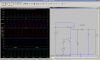
The top transistor would normally be on all the time, because of R1, but Q2 turns it off by pulling its base down when V2 (a square wave with a 73% duty cycle in this simulation) goes high. When Q1 is on, V1 is "charging" the inductor (you can see the purple trace increasing at this stage). When Q1 goes off, the inductor continues to flow current in the same direction, due to energy stored in its magnetic field, but the current is decreasing because it has to drive the load itself, pulling current through D1.

Note that the top trace is the power dissipated in Q1 (average is about 600mW, which is right at the rating for open-air, but still very safe with one of those little push-on heat sinks). The blue trace is the voltage at the output, while the two bottom traces show the voltage at the collector of Q2 and the emitter of Q1.

You would regulate a circuit like this with pulse width modulation and some kind of feedback signal. The easiest thing to do hardware-wise would probably be to generate your PWM signal with a microcontroller (like a PIC) and feed the output voltage back to one of its analog inputs.
 

Attachments

  • Screenshot.png
    Screenshot.png
    26.2 KB · Views: 192
Use (3 ea) LM2575-ADJ switching regulators all of them operating directly from 12V. You will also need (3 ea) 1N5819 diodes, (3 ea) 330uH inductors, and (3 ea) 330 uF 16V electrolytic capacitors. Also, three 100 uF 25V electrolytic capacitors, and (3 ea) 2.0K plus (1 ea) 9.31k, 3.32k, and 931 ohm 1% resistors as described in the ON semiconductor data sheets.
 
I thought you needed a constant voltage source not a constant current source.

Either way check out the Black regulator which can do both.

Official Home Page of Roman Black
 
Status
Not open for further replies.

Latest threads

New Articles From Microcontroller Tips

Back
Top