Continue to Site

Welcome to our site!

Electro Tech is an online community (with over 170,000 members) who enjoy talking about and building electronic circuits, projects and gadgets. To participate you need to register. Registration is free. Click here to register now.

  • Welcome to our site! Electro Tech is an online community (with over 170,000 members) who enjoy talking about and building electronic circuits, projects and gadgets. To participate you need to register. Registration is free. Click here to register now.

Switch H-Bridge with microcontroller

Status
Not open for further replies.

picsmoker

New Member
Hi all!
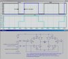
I am busy building a small wheeled robot. My problem is with the switching of the H-bridge. I would like to run the motor from a 8V power source, and the pic from a regulated 5V source. It is in other words, 2 seperate circuits. I am now busy with the prototype on my breadboard, when I ran into a problem. I am using 2X TIP102, and 2XTIP107 transistors, with 1K pulldown resistors, and 1K resistors on the Base. The motor pulls about 1A full load, and 100mA free running.

When I connect the bases to the 8V supply, the motor starts, and runs perfect, but when I connect the bases to the 5V supply, the motor also runs, but the transistors heat up instantly (smoking hot):eek:. I suspect that I am doing something fundamentally wrong here....

I THINK a optocoupler (never used one) might solve my problem, but these babies are a bit expensive. I could use two per bridge (two bridges), but ultemately four per bridge to allow for the motor braking function to work.

Any help and suggestions would be appreciated! I am now stuck on this problem!
 
Post a schematic?

Is the Pic's Vss common to the minus side of the 8V supply?
 
I'm not using the pic at this stage. I'm a bit weary of living up to my name :D
And no, I connected the emitter and collector with the motor to the 8V supply, and used the +5V on the one side of bridge base, and -5V on the other side of the bridge base. It doesn't sound right.... but how should it be done?

I printed the schematic from a website, and forgot to bookmark it. I'll try and find it again to show you what it looks like, otherwise I'll make a new one.
 
I'm going to bed, but I'll try to anticipate your problem. The PNP devices in the top of the HBridge are being driven with a 5V output from the PIC, when the PIC's vss is tied to ground. That means that with respect to the emitter of the PNP, the base is driven either to -3V or -8V meaning it is always ON! That is why it gets stinking hot.

You will have to use an additional transistor stage as a level shifter to properly drive the bases of the PNPs. The NPNs are fine as they are.

I started to simulate it but ran out of time.
 

Attachments

  • HBridge.jpg
    HBridge.jpg
    93.4 KB · Views: 2,557
Last edited:
Found it!

BJT H-bridge Circuit Details

At the moment I just connected the bases on the left and right side of the bridge together. This gives me just forward and reverse. If I could at least get it to work like that, I would be 90% satisfied, but to have the brake working will be nice!

Thinking back to what happened, the PNP's were the ones heating up :rolleyes:
 
How about using a dual H-bridge like the L298?

It just requires three inputs: A, B and Enable. It can provide drive for DC-motors, steppers and solenoids up to 46V at 4A (the entire chip).

Enable can be tied high to control motor direction using A and B inputs. If either one is high and the other low the motor will turn clockwise respectively counterclockwise. If both are equal with Enable high you'll have fast braking.

No worries about smoking transistors.

Boncuk
 
Yes, thanks, it might just solve my problem intantly, but I would still like to get the transistor H-Bridge to work. I'm learning here!

I will investigate how the L298 works, and how it is connected. (or you could help me :)
Something new to learn!
 
Here is the working version of the PIC driven 8V H-Bridge. Read the notes on the schematic.
 

Attachments

  • HBridge.jpg
    HBridge.jpg
    308 KB · Views: 1,490
Here is the working version of the PIC driven 8V H-Bridge. Read the notes on the schematic.

MikeMI, your'e frikkin genius!! Such a simple solution for such a simple problem! I build the bridge last night, and it works perfect! :D:D:D

Would you recommend a small transistor on the NPNs as well to reduce the current on the pic, or is it a waste of time? I understand the TIP102 and TIP107 transistors is a darlington configuration for this very reason?

Thanks again for your trouble. I'm going to show some real progress with my project in the following couple of days.

Ps. what software do you use for your computer prototyping? I seriously want to invest in something like that.
>Thanks also for all the other inputs guys, I'll investigate all those options in due time.
 
...
Would you recommend a small transistor on the NPNs as well to reduce the current on the pic, or is it a waste of time? I understand the TIP102 and TIP107 transistors is a darlington configuration for this very reason?
...
Ps. what software do you use for your computer prototyping? I seriously want to invest in something like that.
...

The current that is sourced by the PIC when CW or CCW is high should be within its capability. Look at the PIC's spec sheet. The current sourced is determined by the base resistors in the H-bridge.

The simulation software is a free download from Linear.com. They call it SwitcherCad or LTSpice. Google it.
 
Status
Not open for further replies.

Latest threads

New Articles From Microcontroller Tips

Back
Top