Continue to Site

Welcome to our site!

Electro Tech is an online community (with over 170,000 members) who enjoy talking about and building electronic circuits, projects and gadgets. To participate you need to register. Registration is free. Click here to register now.

  • Welcome to our site! Electro Tech is an online community (with over 170,000 members) who enjoy talking about and building electronic circuits, projects and gadgets. To participate you need to register. Registration is free. Click here to register now.

Stupid FET Question

Status
Not open for further replies.

Lighty

New Member
Hi all

I've got a stupid question to ask.

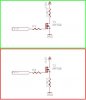
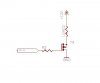
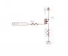
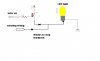
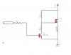
FET's are normally connected between Ground and Load, therefore the load is alway connected to the positive rail....like in the green block of picture

Is it possible to connect it between the load and positive rail like in the red block. The reason I ask is since the circuit will be used on a vehicle in conjunction with existing circuitry and would rather not have 12V running to the load all the time..... If that makes sense.

thanks in advance
 

Attachments

  • IRF530.JPG
    IRF530.JPG
    23.7 KB · Views: 1,289
You show a N-channel MOSFET.

If you use it with load on the high-side, you just need a Vgs signal on the gate to drive it on (usually 5V to 10V depending on the device).

If you connect the load to the low-side, you need a gate signal Vgs higher than the supply voltage and this is usually not a good idea.

If you want the load on the low-side (like in cars) it's better to use a P-channel MOSFET: it will be driven-on putting 0V on the gate.
 
You have selected an N-channel mosfet that usually connects to 0V.
If you use it as a source-follower like in your second sketch then its gate must be at +22V to +24V for it to fully turn on. Its gate must be 10V higher than its source voltage to fully turn on.

Use a P-channel Mosfet instead. Its source goes to +12V and its drain connects to the load which has its other wire at ground. When the gate is at the positive supply voltage then the P-channel Mosfet is turned off. When its gate is at 0V to +2V then the P-channel Mosfet is fully turned on.
 
Either way, the 12V is NOT powering the load all the time. When the FET is turned off, as in your first drawing, there is no current, and thus no power.
 
Ok, something like this?

And if I understand this correctly, when the PIC IO pin is high (+5V) the FET will be off, and when the pin goes low (GND) it will be on?

Any suggestions on the FET, system will be 24V and say 5A....


Am I on the right track with the IRF9Z34N, IRF4905, STP12PF06 ?
 

Attachments

  • IRF P-Ch.JPG
    IRF P-Ch.JPG
    7.8 KB · Views: 726
Now you have the p-type connected to the wrong side of the load. Either connect the p-type FET to the hi side, or use a low side n-type.
 
Wait I got that last schematic wrong, meant to be like this. Load always grounded.....
 

Attachments

  • IRF P-Ch2.JPG
    IRF P-Ch2.JPG
    7.3 KB · Views: 432
rather not have 12V running to the load all the time..... If that makes sense.

Turn off the MOSFET when you don't want power delivered to the load and turn it on when you do. Why does other circuity have an effect?
 
Would something like this work?

R1 feeding 12V from +12V rain, causing T3 to open, when MCU goes high, T1 (N-ch) closes causing R1 and R3 to become a voltage devider, and with the right values, turning T3 (P-ch) on and become closed?
 

Attachments

  • FET driver.JPG
    FET driver.JPG
    17 KB · Views: 878
Last edited:
Mosfets do not open and close.
instead they turn on and turn off.

Yout first Mosfet must be a "logic-level" type so that it turns on with a fairly low input voltage.
 
If you don't speak in English about transistors then we don't know what you are talking about since transistors do not open and close like doors.
 
Would something like this work?

R1 feeding 12V from +12V rain, causing T3 to open, when MCU goes high, T1 (N-ch) closes causing R1 and R3 to become a voltage devider, and with the right values, turning T3 (P-ch) on and become closed?

Yes that should work quite nicely. A 2N7000 series would be good for the first FET.

Bob

PS: I can see gates open and close, just like doors. However your understanding of "open" is the same as an "open" circuit; no conduction. This conflicts with another logical interpretation, that when a flood gate is open, current can pass through. It is best to describe the FET switch as ON or OFF. A positive pulse from the MCU to the gate of T1 turns on T1, causing a negative pulse on the voltage divider to the gate of T3. This turns on T3.
 
Last edited:
Thanks, So I'm getting the hang of this.

So the 2N7000 is ok for the driver, but what about the main switching FET, are these any good?

IRF9Z34N, IRF4905, STP12PF06 ?
 
Status
Not open for further replies.

Latest threads

New Articles From Microcontroller Tips

Back
Top