Hi everyone. I’m asking for some help with this…
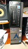
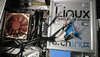
I’m in the process of installing a ASRock X570M Pro4 (Micro ATX) Mobo into a Dell 7010-DT case. I’m used to things just snapping right in all the Mobo sockets and moving right along when I do a PC build but I got tripped up with this project.
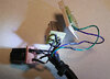
Dell used different types of motherboard connectors on the ends of almost all the cables coming from the front panel. Maybe it’s Dell playing proprietary control games. So, I had to slice off all those end cable connectors and get into figuring out the wiring/pin-outs of everything – and do wire splicing with cables (that have end connectors) that do fit the ASRock MoBo sockets. For the most part, I already have figured things out.
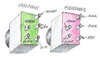
The only thing that I’m currently stuck on is the pin-outs of both the headphone and microphone sockets. I’ve looked online and found pin-outs for other five pin audio sockets – but not ones that have the pins on the back and arranged like these (see photos). The colors written on the image are of the wires attached to those pins.
I don’t know what the:
- assigned pin numbers are for each socket, or
- what purpose each pin handles (ex. Ground/Bias, Shield, Audio Right, Audio Left, Audio Detect/Sense)
Any help would be appreciated. Thanks ahead of time.
I’m in the process of installing a ASRock X570M Pro4 (Micro ATX) Mobo into a Dell 7010-DT case. I’m used to things just snapping right in all the Mobo sockets and moving right along when I do a PC build but I got tripped up with this project.
Dell used different types of motherboard connectors on the ends of almost all the cables coming from the front panel. Maybe it’s Dell playing proprietary control games. So, I had to slice off all those end cable connectors and get into figuring out the wiring/pin-outs of everything – and do wire splicing with cables (that have end connectors) that do fit the ASRock MoBo sockets. For the most part, I already have figured things out.
The only thing that I’m currently stuck on is the pin-outs of both the headphone and microphone sockets. I’ve looked online and found pin-outs for other five pin audio sockets – but not ones that have the pins on the back and arranged like these (see photos). The colors written on the image are of the wires attached to those pins.
I don’t know what the:
- assigned pin numbers are for each socket, or
- what purpose each pin handles (ex. Ground/Bias, Shield, Audio Right, Audio Left, Audio Detect/Sense)
Any help would be appreciated. Thanks ahead of time.