Continue to Site

Welcome to our site!

Electro Tech is an online community (with over 170,000 members) who enjoy talking about and building electronic circuits, projects and gadgets. To participate you need to register. Registration is free. Click here to register now.

  • Welcome to our site! Electro Tech is an online community (with over 170,000 members) who enjoy talking about and building electronic circuits, projects and gadgets. To participate you need to register. Registration is free. Click here to register now.

Strobe lamp fixing

Status
Not open for further replies.

met91189

New Member
Hello guys!
A friend of mine gave me a strobe lamp to fix (an economic one, 1500W) that he would repair.
The lamp doesn't have a brand on it, but googling I figured out that it's a really common model produced by many brands (KARMA, Proel ecc.).
My first problem is that my friend disconnected the cables from the PCB (the supply cables and the 3 cables of the strobe lamp) and he doesn't remember how they were connected. Since I can't find a scheme of the circuit I can't find out how they should be connected.
Is anyone available to give me a help fixing the lamp?
I attach pictures of pcb and wires
lampada1.JPG lampada2.JPG lampada3.JPG
 
What is the red wire going to? It looks like some kind of switch, but I can't tell from the picture.

You have some significant diodes behind the potentiometers - that's probably where power comes in. What kind of strobe light is connected? What signal do they need to work properly? In other words, would they need a DC pulse or some kind of AC signal? This can help you in defining the input and output parameters of each block.

If the other blocks are for the strobe lamps, does it matter which lamp is connected to which block?

If the block with the red wire is for the power supply, then you can test the other blocks to see what they are doing after power is applied to determine which lamp goes where if it matters. I assume the pots make changes to period or duty cycle?

If you don't like assuming the power block, you can try injecting a low voltage AC sine from a function generator and looking on other blocks with an o-scope to see what you get. My guess is the outputs will be square waves., but that kind of depends on the answers to the first question about the kind of lamps being driven.
 
Hi,

Take the datasheet from the DIP IC and go backwards, it's probably the key from the complete circuit so you will understand the theory of operation finding inputs and outputs.
 
I love it when people take things apart and expect you to put them back together again...

Firstly, the obligatory warning: Strobe lamps are very dangerous - that entire circuit is live at mains potential, and will (when it's working) be producing spikes of several kV. But I'm sure you allready knew that!

In case you're not familiar with them, strobe tubes are a xeneon discharge lamp with two main terminals and a trigger. The main terminals are at oposite ends of the tube inside the gas, while the trigger is usually a fine wire running over the outside of the tube, electrically isolated from the gas. A voltage is applied between the main terminals which, in itself, is not high enough to ionise the gas and strike an arc. To fire the tube, a very high voltage and very short pulse is applied to the trigger - this couples capacatively through the glass and ionises the gas. Once ionised, the gas conducts a current between the main terminals (lighting up as it does so). The arc will be sustained until the current falls below the holding current of the tube.

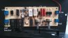
I've had a look over your photos, and think it's something as follows:

The tube is directly in series with the mains, via the large diodes D2, D3. This is common; once fired, the tube can conduct for (at most) one half-cycle. On the second half-cycle the diodes block and the tube has time to extinguish. C4 is accross the tube (and seems to be charged through C3 and a diode). When the tube fires, it will absorb all the energy from C4 and then contuniue to conduct for the rest of the half-cycle.
The trigger pulse is produced at the secondary of T1 and applied between Lamp2 and the Trigger terminal. To generate this pulse, Q1 conducts and discharges C1 through the primary of T1 into Neutral. C1 is then re-charged via D1 and R1 from the Line conductor. Q1 looks like it might be a Triac and is driven by Q2 via a capacitive coupling C5. Could this be a relaxation oscilator? I'm not sure if Q2 is driven from the DIP16 or the optocoupler... It's hard to be know how the control is done.
The low voltage supply for the IC seems to be dropped through R2 and the diode that's hiding underneath it, with C2 being the reservior capacator - could that be a zener diode lurking behind it?

Please understand that I can't be sure about any of this, so please satisfy yourself that it makes sense before connecting up mains to your board and ruining it because I was wrong!

I'd start fault finding by checking T1 for continuity; you'll see it only has three connections - the two widings will be commoned at the Neutral point.
Then apply some power (need not be full mains) and see if you're getting any voltage on C2.

It would help us to know the part numbers are on the components, and how the controls and connectors are labeled.

Hope this helps - let us know how you get on (and be CAREFUL).
 

Attachments

  • strobe.jpg
    strobe.jpg
    161.5 KB · Views: 197
Hello everyone!
You've been so kind and I thank you all!
tomizett I really liked your analysis and now I integrate my pictures with some more details:
the IC in the center is an MC14093BCP,
unfortunately the white piece near the IC is not readable (I only read 0408, but I'm not sure)
the Q1 is a Triac BTA06 600C.
Do these details add some more reliability to your review?

Mity Eltu the red and brown wires are directly coming from the alternative current ( there is also a 15 A fuse) the 3 other wires are coming from the lamp.
 
Last edited:
So... the MC14093BCP is a Schmitt trigger NAND - this is probably configured as two oscillators. I'm guessing that the lamp produces burst of flashes, and the two knobs control how fast the flashes happen and how long the burst are, or something? This would likely be done with two oscillators (one fast and one slow), with one gating the other.
The white 8-pin IC is an optocoupler of some kind, but I'm not sure of its function yet.

Regarding the lamp, the two main terminals will be coming from each end of the tube, and will clearly be passing through the glass. The trigger terminal will be coming from the outside of the glass, and may have a thicker insulation on the wire.

Start by checking the small transformer T1 (with the power off). You should read a few ohms between all three pins.
 
So... the MC14093BCP is a Schmitt trigger NAND - this is probably configured as two oscillators. I'm guessing that the lamp produces burst of flashes, and the two knobs control how fast the flashes happen and how long the burst are, or something? This would likely be done with two oscillators (one fast and one slow), with one gating the other.

Strobes aren't that clever - you just have a single oscillator for the flash speed, the timing of the flash is set by the size of the storage capacitors and the rating of the strobe tube. It's fairly difficult to turn a flash OFF part way through, it would make it far more expensive, and use more than double the parts - plus there's no need for it.

Incidentally, I have two strobes at home that I was given, both were written off by a music shop repair agent, and both just needed new strobe tubes - it's by far the main thing that fails in strobes (they are only rated for a limited number of flashes).
 
Actually, yes - that's a good point that I forgot to mention: It may just be that the tube is worn out, especially if it's performance has been getting worse for some time. Have a *good* look to make sure it's not cracked...

I wouldn't be so sure about the control circuitary though. I believe that, in this case, the power side of things makes itself "ready" (ie C1 and C3 charged) within a cycle or two of the mains, and is then triggered to fire by a sepperate control sytem. As I say, it's a bit hard to guess without any knowledge of what controls are visible to the user.
Here, the main energy supplied to the tube comes directly from the mains, rather than from a storage capacitor as in a camera flash, so there's no charging time-constant to limit the maximum repeat rate.
As NG says, it's very difficult to turn the tube "off" on demand - this design ensures that the arc is quenched during the half-cycle when D2 and D3 block.

My educated guesswork (and it is only quesswork, mind!) is based on the big professional strobes I've worked on - this design looks fundamentally pretty similar.
 
You have audio sockets on the PCB that you plug in to your amplifier, if you connect mains to the board you will blow the board and your amplifier. There must be a transformer to power the board.
There is no such thing as xenon tube connected directly to mains. You must have a large electrolytic cap and diodes and resistors to charge it, it is likely to be on the missing board that has the transformer.
 
I suspect that the 1/4" jack connectors are for some kind of remote control or foot switch - they do not appear to be isolated from the mains and should NOT be connected to any kind of audio equipment. This is the kind of corner cutting that can make some cheap gear dangerous.

There is no such thing as xenon tube connected directly to mains.
Well, I was surprised the first time I saw it done, but it *is* the way some high power strobes work.
If there is a power transformer in the case then I'm mistaken in my interpretation of the circuit, but the OP does not mention one.
 
Hey tomizett, I tried all you said and finally your configuration worked!!
Thanks a lot for all you did and I hope that this post will be useful for all those who will have similar problems.
The circuit is directly connected to the mains through the red and brown wires, I confirm that there is no power transformer.
For any further doubt I will reply. Thank you again to all those who spent a little time trying to help me. :)
 
Status
Not open for further replies.

Latest threads

New Articles From Microcontroller Tips

Back
Top