Continue to Site

Welcome to our site!

Electro Tech is an online community (with over 170,000 members) who enjoy talking about and building electronic circuits, projects and gadgets. To participate you need to register. Registration is free. Click here to register now.

  • Welcome to our site! Electro Tech is an online community (with over 170,000 members) who enjoy talking about and building electronic circuits, projects and gadgets. To participate you need to register. Registration is free. Click here to register now.

STM32F103VET6 and CH340G

Status
Not open for further replies.

gazy98

New Member
I have a problem with my PCB. I recieved it a few days ago and it is
already completly presoldered. If i connect it via USB-TYPE B to my pc
it is showing me nothing in device menager.... The CH340G should be
visible to be able to programm it via usb....
If i connect an ARDUINO MEGA with ch340 it is visible so there shouldnt be an driver issue. But i still made updates to the drivers a few times just to be safe.....

If i connect it via micro-usb unknown device is popping up. But that
does not help me :).

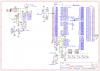
I have added the schematic. Hope someone can help me.
 

Attachments

  • Schematic_INTERFACE PCB_Sheet_1_20200120130255.png
    Schematic_INTERFACE PCB_Sheet_1_20200120130255.png
    98.4 KB · Views: 239
If memory serves, I have made the the same mistake. I believe the CH340 V3 pin needs a cap to ground. I think I use 100nF.
 
I made connection with 100nf Cap but it still does not show up in device menager.... can there be a problem with the X2? i dont no much about it .... i just added a 12Mhz because it was written in the Datasheet...

Thanks for the Drawing. It is now exactly like yours connected but still nothing...
 
Do you have a crystal or an oscillator? Your schematic shows 4 leads, so it looks like an oscillator. I don't think an oscillator needs loading caps, and it does need power and ground connections.
 
According to the datasheet, V3 needs to be VCC. I trust sparkfun to get things right.

Mike.
Edit, check the schematic on page 5.
Edit2, I assume you're using 3.3V.
 
...if you are using 3.3v....

This schematic I posted is a proven, well tested design for a 5 volt system. And uses the capacitor to ground as shown in the data sheet. Read the descriptive text.
 
...if you are using 3.3v....

This schematic I posted is a proven, well tested design for a 5 volt system. And uses the capacitor to ground as shown in the data sheet. Read the descriptive text.
Isn't the STM max voltage 3.6V hence my edit above.

Mike.
 
The OP's schematic isn't using 3.3v from the CH340 – there's a separate 3.3v linear regulator. I don't know how much current the CH340G can supply.

I left off the V3.3 cap in my first design using the CH340G with a 5v micro, so I recognized the problem immediately.
 
The OP's schematic isn't using 3.3v from the CH340 – there's a separate 3.3v linear regulator. I don't know how much current the CH340G can supply.

I left off the V3.3 cap in my first design using the CH340G with a 5v micro, so I recognized the problem immediately.
Ahh, hadn't noticed that. I wonder how the STM likes it's pins being driven at 5V?

Mike.
 
Ahh, hadn't noticed that. I wonder how the STM likes it's pins being driven at 5V?

Depends on the pin in question. All most all of a STM32's pins will be 5V tolerant(F0, F1 & F3 at least), except those that are used for analog functions.
In this case, PA9 and PA10 are 5V tolerant, so it won't care if you drive them at 5V...
 
Status
Not open for further replies.

Latest threads

New Articles From Microcontroller Tips

Back
Top