Hi
i need some guidelines for the repairing of an old home theater...
probably some of you will say "why i bother and i don't get a new one"...
i'm not fan of such devices but if i manage to repair it i will make a
friend happy")
the model is Philips HTS3164, the VFD is not working neither the power led..
there's no video output, thus looks like a dead unit.
the power supply voltages seem fine .. 12V, 32V (for the amplifier), 5V, also manually
ejecting the DVD tray it automatically closes when you connect the device to the
mains...also some of the ICs on the main board they do power on becauce
they get a little bit warm.
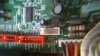
i'm thinking the problem might be the standby circuit...in the following
picture / schematic seems the standby is controlled by an MCU... P89LPC931
(it's the fine pitch IC in the second picture over the connector)
i need your help to diagnose if the problem is the standby circuit because
i'm not that expert with such kind of repairings...but i'm able with a little
bit help.
thank you
i need some guidelines for the repairing of an old home theater...
probably some of you will say "why i bother and i don't get a new one"...
i'm not fan of such devices but if i manage to repair it i will make a
friend happy
the model is Philips HTS3164, the VFD is not working neither the power led..
there's no video output, thus looks like a dead unit.
the power supply voltages seem fine .. 12V, 32V (for the amplifier), 5V, also manually
ejecting the DVD tray it automatically closes when you connect the device to the
mains...also some of the ICs on the main board they do power on becauce
they get a little bit warm.
i'm thinking the problem might be the standby circuit...in the following
picture / schematic seems the standby is controlled by an MCU... P89LPC931
(it's the fine pitch IC in the second picture over the connector)
i need your help to diagnose if the problem is the standby circuit because
i'm not that expert with such kind of repairings...but i'm able with a little
bit help.
thank you
Attachments
Last edited:
