Continue to Site

Welcome to our site!

Electro Tech is an online community (with over 170,000 members) who enjoy talking about and building electronic circuits, projects and gadgets. To participate you need to register. Registration is free. Click here to register now.

  • Welcome to our site! Electro Tech is an online community (with over 170,000 members) who enjoy talking about and building electronic circuits, projects and gadgets. To participate you need to register. Registration is free. Click here to register now.

Square input problem

Status
Not open for further replies.

zesla

New Member
Hi guys,

Why the yelow waveforms does not swings Around the zero??!
When The input is a sine wave it nicely swings around zero but when the wvaeform is square wave then the below pic happens!?
Is that natural? Unfortunately it causes the output to not swings around the zero axis too.

What's the solution?

Thanks.
 

Attachments

  • qw.PNG
    qw.PNG
    65.9 KB · Views: 134
Last edited:
of course the LO and HI power supply voltages are +- 7,5V

hi,
Trying running the simulation for much longer and see what happens with the square about 0V.

Have you done a frequency analysis of your circuit for its response.???
Consider a sine wave compared to a square wave response in a limited bandwidth circuit.
 
the feed back may take sometime to stabilize, so if you run the simulation for 50 ms, it may clamp it down.
 
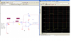
The Spice simulator does a "initial dc bias solution" before allowing all the circuit nodes to be determined as a function of time. During the bias solution, the input voltage source is set to -1mV. Since the opamp + input is grounded, the - input must be essentially at ground. Since during a DC solution there can be no steady-state current through the input coupling capacitor, the current in the input resistor, and the feedback resistor must be zero as well. That means that the input capacitor must be charged so that its left end is at -1mV, while its right end is at 0V. As the simulation begins, the input voltage source varies from -1mV to +1mV, with an average value of 0V. So to go from a net -1mV to 0V across the capacitor, the capacitor must "discharge" through the input resistor with a time-constant of R1*C. That "discharge" curve is super-imposed on the normal square-wave that comes from the input signal.

This behavior matches the real world. Any amplifier with a DC blocking capacitor at its input will follow a step input, and then that will revert back to its previous level with a time-constant of RC.

A simple solution to making the turn on transient disappear from your sim is to use the .IC (initial conditions) at the opamp - input node to -0.5mV. Another is to just simulate for a longer time, and then only plot the output after the initial transient has died out.
 
Last edited:
hi,
This is a longer sim, it highlights the point that Mike and I are making.
I have added the analysis for reference only.
 

Attachments

  • AAesp02.gif
    AAesp02.gif
    25.4 KB · Views: 156
  • AAesp01.gif
    AAesp01.gif
    30.8 KB · Views: 143
Oh, Yea, Thanks for all inputs,

I increased the simulation time and the problem was solved.

Thanks again
 
Status
Not open for further replies.

Latest threads

New Articles From Microcontroller Tips

Back
Top