Continue to Site

Welcome to our site!

Electro Tech is an online community (with over 170,000 members) who enjoy talking about and building electronic circuits, projects and gadgets. To participate you need to register. Registration is free. Click here to register now.

  • Welcome to our site! Electro Tech is an online community (with over 170,000 members) who enjoy talking about and building electronic circuits, projects and gadgets. To participate you need to register. Registration is free. Click here to register now.

Sprinkler Flow Sensor help

Status
Not open for further replies.

cswanson

New Member
I'm going to try and sound as intelligent as I can about this. I was an EE minor in college, so I remember some stuff ;-)

I'm getting lawn sprinkler leaks, and I'd like to know exactly when my water in the irrigation system is flowing. I don't care how much is flowing, just an ON/OFF signal.

There are several flow sensors on the market, this seems to be the best one not completely locked into a proprietary controller:

- **broken link removed**

It says:

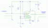
The flow sensors generate a frequency which is proportional to flow
rate.... Power to operate the sensor is provided by the flow monitor... As
the liquid flow turns the impeller, a low impedance signal is transmitted
with a frequency proportional to the flow rate.

Like I said, I really just want ON/OFF, YES/NO.. so I can control a light or chirping buzzer with a relay or something.

Is there a fairly easy way to:
- send it power? 5V? 12V
- Determine that ANY "a low impedance signal" is being sent?

I'm handy with a soldering iron and a volt meter.. but not with this type of detail. I clearly don't want the $200-$500 full solution,
a $100 sensor and some misc bits is what I want.

Thoughts?

Any help is much appreciated, and in return, I'll give back and put up a nice final project description and pictures to help others out.

Carl
cswanson2web@gmail.com
 
It looks like the sensor makes pulses of low impedance (15R + 0.7V) as the rotor turns. If you want to detect any single pulse and turn on a buzzer, you can try the attached cct. Any detected pulse triggers the LM555 timer IC, which sends ~12V to the buzzer for ~11 seconds after the last pulse.
 

Attachments

  • BUZZER.gif
    BUZZER.gif
    6.6 KB · Views: 225
Last edited:
Are you trying to measure an extremely low flow? You mention leaks. The problem with most flow sensors is that they have a range at which they will operate and if the flow rate of concern is well below that the sensor may not provide the information you need.

Sound could be a useful indicator - audible or ultrasonic sounds are a part of flow. The lack of sound might reveal a no-flow condition.
 
It looks like the sensor makes pulses of low impedance (15R + 0.7V) as the rotor turns. If you want to detect any single pulse and turn on a buzzer, you can try the attached cct. Any detected pulse triggers the LM555 timer IC, which sends ~12V to the buzzer for ~11 seconds after the last pulse.

Dougy, that's awesome.. thank you... so I guess that follows two questions:

- as the next poster said, will this detect very low flow? Typically when it leaks, it leaks big, but it might leak small, I just don't know....

- this is supplying power to the unit as well you think? Is that what this means "Power to operate the sensor is provided by the flow monitor"?

Thank you much for the help dougy, much appreciated!

Carl
 
From the quick look I had at the datasheet, it looks like the sensor is supplied current through its 2 wires, and will short-circuit (connect a low impedance between them) them every time it outputs a pulse. Power is supplied from the 12V supply through the 1k resistor in the above diagram. EDIT: Be sure to connect the sensor around the correct way: + to the 1k resistor, - to the 0V.

From the datasheet, it says the sensor is 1% accurate for flow rates of 0.5-30'/sec. I can only guess that it will work outside this range with varying degrees of accuracy. Obviously I have no idea of how small a leak can be detected.
 
Last edited:
You guys may be able to make one of these at much lower cost:
$185!! I would think it could be made cheaper - especially for just a go/no go output. A couple of waterproofed thermistors, each biased with a different current plus a comparator would do the trick.
 
I am trying to understand your situation and how a leak might be different from normal flow. I am trying to imagine a diagram of your system (the piping). I am thinking that there is a control valve that opens and closes - upstream of the control valve is the water supply - downstream are the sprinkler heads.

If there is a place where water is trapped under pressure - and a drop in pressure could indicate a leak then measuring the pressure for a short period of time after valves have close might reveal a leak.

It might be possible to measure the flow rate vs pressure to characterize the system with known good condition of the piping system. You would then monitor the flow vs pressure and signal an alarm when flow deviates significantly from normal - on the assumption that a leak would result in greater flow. The problem is that this method would not be particularly useful for small leaks.

Great response stevez, and everyone really. The real thing I'm looking to do is just this: When water is flowing, I get a signal.... for whatever reason... small leak, broken section, normal watering, etc. I'm already putting in a somewhat unusual master 1 1/2 valve after the backflow to only turn on the main when I set that to open up... so this flow sensor is really just a triple check... but once you blow a main sprinkler valve and lose several thousand gallons of water (and $$$), you get a bit skittish... at least I do. Living in Texas, you can imagine that water is pretty expensive.

Carl
 
Last edited:
If someone finds a sensor that will detect a very slow leak, then I would be very interested. Last year, I got a slow leak in my guest bathroom ( rarely used ) and by the time I discovered it, I had a $200 water bill, and a bad mold problem in my basement.
 
Last edited:
As for the slow leak... the water meter is actually very sensitive.. my little triangle spins with only a tiny toilet leak.... so in my next life, I'd just get a sensor that could watch that triangle spin... or something like that.... but that just struck me as kinda crazy.... but if someone has an idea for that ;-)
 
Now that I understand the problem a little better I'd offer this comment. Something tells the sprinkler system to be on or off. In the "on" condition the flow rate should be quite different and within a predictable range. The same would be true of the off condition. You could have two parallel flowmeters - a high flow meter and a trickle flow meter. You might add a check valve to the high flow meter that will add a bit of drag. During high flow periods the low flow path would force the flow thru the high flow path and meter - your timer or whatever it is would indicate that high flow is expected and you would then compare normal high flow to what might be an abnormal condition.

During low flow the extra resistance of the high flow path would force what little water moves thru the low flow meter - hopefully at a rate that provides the indication. The timer would be indicating that an "off" condition is expected with corresponding low or no-flow rates. This might be a good application for a PIC or similar device.
 
Status
Not open for further replies.

Latest threads

New Articles From Microcontroller Tips

Back
Top