Continue to Site

Welcome to our site!

Electro Tech is an online community (with over 170,000 members) who enjoy talking about and building electronic circuits, projects and gadgets. To participate you need to register. Registration is free. Click here to register now.

  • Welcome to our site! Electro Tech is an online community (with over 170,000 members) who enjoy talking about and building electronic circuits, projects and gadgets. To participate you need to register. Registration is free. Click here to register now.

Split supply

Status
Not open for further replies.

stef10

New Member
Hey guys, in a circuit im trying to establish a 12V, -12V voltage sources. I have an op-amp which requires it.

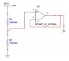
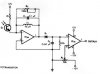
My teacher gave me a hint that if you had a regular 12V voltage supply it was possible in a way to use virtual grounds and voltage dividing with resistors and an op-amp to achieve this although I dont see exactly how. Hopefully you have some answers.

Thanks.
 
You won't be able to get +/- 12V from a 12VDC supply using a virtual ground, you'll get +/-6V.

If depends on the circuit, post a schematic.
 
he made this
 

Attachments

  • split supply..JPG
    split supply..JPG
    16.6 KB · Views: 141
That's a viertual ground, how about the rest of the circuit?
 
he made this

That puts a virtual ground half way between 0V and 12V, effectively splitting the world so you have -6V and +6V relative to the virtual ground, NOT -12V and +12V.

And because your teacher used power-wasting 100Ω resistors to create the voltage divider, he/she obviously lacks real world experience.
 
Last edited:
well, he only gave me this as a hint and said I could from this supply the op-amp with 12V, -12V
 
well, he only gave me this as a hint and said I could from this supply the op-amp with 12V, -12V
He is in error. With a single 12V supply, you can only generate ±6V using a virtual ground.
 
It'll probably run from +/-6V otherwise he wouldn't have suggested that.

We can't help you because you haven't posted the schematic for the circuit you want to power.
 
its mainly this circuit, does it really need +12V and -12V or can we just use 6V?
 

Attachments

  • Receiver..JPG
    Receiver..JPG
    21.5 KB · Views: 138
What is IC2a/b?
 
it is an op-amp

What opamp. I was going to look up the specs on its data sheet (which is what you should do, if you did you would not have posted your question)
 
I was more questioning it the 12V was for another part of the circuit and not for the op-amp. But at first I need to consult with my teacher because im not sure if we have these kinds of op-amps.

Thanks for the help, I will post again if I have a question my teacher might have messed up:)
 
It's important to know what type of op-amp is used so you know it'll work down to +/-6V.

You just connect the ground symbol on the second circuit to the output (pin 3) of the op-amp in the first circuit.

R1 and R2 on the first circuit should be increased to save power (try 10k) and a 100nF capacitor should be connected across either of them.

You should use a quad op-amp if possible to save money and space.
 
Status
Not open for further replies.

Latest threads

New Articles From Microcontroller Tips

Back
Top