Continue to Site

Welcome to our site!

Electro Tech is an online community (with over 170,000 members) who enjoy talking about and building electronic circuits, projects and gadgets. To participate you need to register. Registration is free. Click here to register now.

  • Welcome to our site! Electro Tech is an online community (with over 170,000 members) who enjoy talking about and building electronic circuits, projects and gadgets. To participate you need to register. Registration is free. Click here to register now.

Split charge system

Status
Not open for further replies.

arunpandiant24

New Member
Hi,

I want to design the circuit board for the Automatic main battery and auxiliary battery link to charge when the engine is running. with your supports.

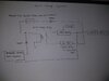
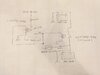
When the engine is running, the alternator provides power for charging the main battery. Auxiliary battery backup support, when the main battery is dead, the main battery can be started by the manual link switch to start the engine. The alternator is generated at a voltage of 13.7V to over 15V. the main battery powers all accessories

Automatic battery link system:

The automatic battery link system will monitor the main battery. Once the main battery reaches 13.7V or more, the system should link the main and auxiliary batteries, which means that the engine is running. The main battery voltage is lower than 13.7V, the system will automatically cut off the power, which means that the engine is off.

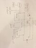
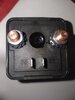
I have attached the split charge system layout for your reference. I hope it can be better understood better.

Thank you for your assistance.

I hope everyone is doing well.

Thanks,
Arun
 

Attachments

  • Split charge system.jpeg
    Split charge system.jpeg
    44.8 KB · Views: 253
Your circuit diagram is a bit odd. I think that in principle it's OK, but the two rectangles that are the batteries should just be interconnections. Each battery should have its negative permanently connected to ground.

There are a lot of systems that will do what you want already.

Depending on what this is fitted to, the alternator may change its voltage depending on conditions. A lot of modern cars do that.
 
hi,

The vehicle starts and all accessories work on the main battery.

Auxiliary battery – used as a backup for starting when the main battery fails.

If both batteries are connected in parallel, the auxiliary battery will die when the main battery fails, so batteries are isolated to prevent problems.

When the engine is running, I need to charge both batteries automatically, and I need your help to make the circuit.
 

Attachments

  • 1.jpeg
    1.jpeg
    42.4 KB · Views: 198
Auxiliary battery – used as a backup for starting when the main battery fails.
That will require a high current (starter type) relay to connect the backup battery and should likely be separate from the charging relay, since starter relays are not normally continuous duty.
Is that what you were planning?
 
Last edited:
That will require a high current (starter type) relay to connect the backup battery and should likely be separate from the charging relay, since starter relays are not normally continuous duty.
Is that what you were planning?

Hi,

Please find the attached Split charge system layout which is currently used.

The main & aux batteries are linked to charge When pressing the link switch- the engine is running condition.(Batteries continue to charging,until the engine is turned off, even after release the link switch).

When the engine is running, press the switch for the battery linked to charge every time.

As a result, I'll have to build an electronic circuit for the battery to charge automatically while the engine is running.

In the previous Post, I added a proposal layout.

Thank you in advance.

Regards,
Arun
 

Attachments

  • split charge system (Currently using).jpeg
    split charge system (Currently using).jpeg
    44.7 KB · Views: 202
Is that 12V, 200A relay continuous duty?
 
If you parallel a fully charged auxiliary battery with a discharged main battery, you won't necessarily be able to start the vehicle.

The Aux battery will dump it's charge in to the main battery.

As for automatically charging the Aux battery when the vehicle is running, all you need are two heavy current diodes, the Anodes of which connect to the charging system and each Cathode to one each of the batteries. The alternator may need to be adjusted to accomodate the voltage drop across the diodes if it is not the intelligent type that does it automatically.

Also, I think you'll find there is already a commercial system available that does what you want - check with 4x4/offroad places or even your local auto electrician.

Hi,

My systems are not to be connected in parallel. The relay is used to separate both batteries. I need to be connected in order to charge both batteries when the engine is running and to detach both batteries when the engine is turned off.


Actually, my configuration isn't connected automatically. I need to press the link switch to connect the batteries, which will then be automatically isolated when the engine is turned off ( this condition is fine).


So I'll need your help to create a circuit, and once the engine is running, the circuit can send power to the relay coil(the circuit sense the voltage level and the relay will link the batteries for charging).


Regards,
Arun.
 
So I'll need your help to create a circuit, and once the engine is running, the circuit can send power to the relay coil(the circuit sense the voltage level and the relay will link the batteries for charging).
Why not just power the relay from the ignition switch accessory power circuit, which is off when the engine is starting, but active when the ignition is on?
 
Why not just power the relay from the ignition switch accessory power circuit, which is off when the engine is starting, but active when the ignition is on?

Hi,
Ok, the power the relay from ignition, when engine is not cranked - the both batteries are discharged and the vehicle accessories are active on the ignition switch on condition.
The Aux battery will not be able to provide enough power to start.

I'm looking for a voltage sensitive circuit schematic that input will be connected to the main battery And I need the 12V/1A output voltage for relay coil energized, once the main battery has reached 13.V or higher(engine is running).

Regards,
Arun.
 
I need the 12V/1A output voltage for relay coil energized, once the main battery has reached 13.V or higher(engine is running).
Below is the LTspice simulation of a circuit that uses the common TL431 programmable shunt reference as an accurate comparator to turn on the relay when the voltage is above the set point.

The TL431 conducts and turns on the P-MOSFET when the Ref voltage provided by the voltage divider R2-R3 from the battery voltage (Vb) goes above 2.5V.
An increase or decrease in R2 will increase or decrease the trip voltage (here shown as Vb ≈ 13.1V for the given values).
R2 can be a 50kΩ pot if you want the trip voltage to be readily adjustable.

R6 provides some hysteresis so the relay doesn't chatter around the set point, causing the relay to drop out at about 0.27V below the upper set point or Vb ≈ 12.9V here.

The LED D1 provides an indication that the relay is energized.

The transistor can be just about any standard (not logic-level type) P-MOSFET with a ≥50V and and Rds(on) of ≤0.5Ω rating.

The circuit can be built on a small perf board.

1620136881758.png
 
Last edited:
Below is the LTspice simulation of a circuit that uses the common TL431 programmable shunt reference as an accurate comparator to turn on the relay when the voltage is above the set point.

The TL431 conducts and turns on the P-MOSFET when the Ref voltage provided by the voltage divider R2-R3 from the battery voltage (Vb) goes above 2.5V.
An increase or decrease in R2 will increase or decrease the trip voltage (here shown as Vb ≈ 13.1V for the given values).
R2 can be a 50kΩ pot if you want the trip voltage to be readily adjustable.

R6 provides some hysteresis so the relay doesn't chatter around the set point, causing the relay to drop out at about 0.27V below the upper set point or Vb ≈ 12.9V here.

The LED D1 provides an indication that the relay is energized.

The transistor can be just about any standard (not logic-level type) P-MOSFET with a ≥50V and and Rds(on) of ≤0.5Ω rating.

The circuit can be built on a small perf board.

View attachment 131204

Hi,

Thank you so much for your hard work on this. I working on it and I will update status soon.

I very much appreciate your help

Regards,
Arun
 
Do you need any help with building the circuit?
 
.
 
This is a really good idea, if you can make it should be very good, I hope you can upload the full code and video demo when the project is finished.
 
Very succinct.

I had multiple windows open and wrote a great answer to the wrong post. It was so good, it might have answered this thread as well. But this is a weird forum, no chance to delete a post.
 
Do you need any help with building the circuit?

Hi,

Thanks for your supports,

I ordered all components except IRF7343P Mosfet, even i checked with local market. i did not get this part.
alternatively IRF7316 ,IRF7425 ,IRF4905,IRF9630 available.

Please advise me .
 
Status
Not open for further replies.

Latest threads

New Articles From Microcontroller Tips

Back
Top