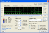
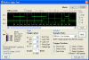
Here is an SPI routine that is not working - see attached analyzer log.
For some reason the Serial Out (SO) line (when high) is falling at clock rise but I can't figure out why. Any ideas? Perhaps it's staring me in the face because I've been debugging it for too long. Probably just need somebody else to have a look...
Any thoughts?
..or is it an electrical problem? Do I need any resistors or other components between the PIC12F675 and the ENC28J60? Currently it is a direct connection on a breadboard.
Thanks,
David
For some reason the Serial Out (SO) line (when high) is falling at clock rise but I can't figure out why. Any ideas? Perhaps it's staring me in the face because I've been debugging it for too long. Probably just need somebody else to have a look...
Code:
;-----------------------------------------------------------------------------------------------------------------------------
; SPI subroutine
; ==============
;
; Call with:
;
;  spi_count set to the number of bytes to write/read
;  spi_in set to the first register address of the inbound buffer
;  spi_out set to the first register address of the outbound buffer
;-----------------------------------------------------------------------------------------------------------------------------

spi
	movlw	spi_in1
	movwf	spi_in		; Set the start of the inbound buffer
	movlw	spi_out1
	movwf	spi_out		; Set the start of the outbound buffer

	movlw	8		; Set bit counter
	movwf	spi_bit		;   to 8 bits

	bcf	GPIO,2		; Set CS line low

spi_looplong
	nop
	nop
	nop
	nop
	nop
	nop
	nop

spi_loop
	movf	spi_out,W	; Point to next spi_out byte
	movwf	FSR		;   with File Select Register
	rlf	INDF,F		; Roll next data bit into Carry flag
	btfss	STATUS,C	; Is it high? If yes, skip...
	goto BitLow

	bcf	GPIO,1		; **** Set clock line low ****
	bsf	GPIO,4		; Set SO line high
	goto spi_donebit	; We have done the bit, continue on...

BitLow
	bcf	GPIO,1		; **** Set clock line low ****
	bcf	GPIO,4		; Set SO line low
	nop			; Wait an extra cycle if BitLow to match high alternative

spi_donebit
	nop
	nop
	nop
	nop
	nop
	nop
	nop
	nop
	nop
	nop
	nop
	nop
	nop
	nop
	nop
	nop
	nop
	nop
	nop
	nop
	nop
	nop
	nop
	nop

	bcf	STATUS,C	; Clear the Carry flag

	bsf	GPIO,1		; **** Set clock line high ****

	btfsc	GPIO,5		; Read bit from SI line, skip if clear (0)
	bsf	STATUS,C	; Set the Carry flag if bit not clear (1)
	movf	spi_in,W	; Point to next spi_in byte
	movwf	FSR		;   with File Select Register
	rlf	INDF,F		; Roll the incoming bit into the buffer

	nop
	nop
	nop
	nop
	nop
	nop
	nop
	nop
	nop
	nop

	nop			; Wait an extra cycle to match other side of clock

	decfsz	spi_bit,F	; Decrement bit counter, skip if zero
	goto spi_looplong	; Go do next bit...

	decfsz	spi_count,F	; Decrement our byte counter, skip if zero
	goto spi_nextbyte	; Go do next byte, otherwise...
	nop			; Wait 210ns (each instruction is 1us or 1000ns)

	nop
	nop
	nop
	nop
	nop
	nop
	nop
	nop
	nop
	nop

	bsf	GPIO,2		; Set CS high
	return			; Return to program

spi_nextbyte
	movlw	8		; Reset bit counter
	movwf	spi_bit		;   for next 8 bits
	incf	spi_out,F	; Point to next byte in outbound buffer
	incf	spi_in,F	; Point to next byte in inbound buffer
	goto spi_loop		; Go do next byte...
Any thoughts?
..or is it an electrical problem? Do I need any resistors or other components between the PIC12F675 and the ENC28J60? Currently it is a direct connection on a breadboard.
Thanks,
David