Hello everyone..
I have pulled apart a circuit because a friend reported it stopped working..
I already know Jaycars Speedo Corrector Circuit from past experience,
thats what I found inside, tho it contained a small circuit board also.
This circuit is used for a Truck. Something about changed engine, and need ECU to recognise real speed to stop the truck maxing out at 50km/h etc...
I have used this circuit in my cars previously and allow my Speedometer to change 99% +/-
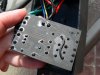
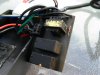
All parts have been sprayed BLACK to not able to duplicate this circuit, so repairs are more difficult.
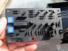
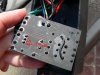
But this circuit has an additional Board, containing (2x Small relays, signal Diode I think..., inline speaker transformer... I think.. it's a tiny transformer.)
The Diode - It looks like a small signal diode, but without a black stripe to the side... if anything the stripe looks in the middle
The 2 relays - these are used for disabling the correction and allowing sensors to bypass the Circuit,
Transformer - The speedo sensor wires when connected to the speedo corrector go throu the diode and transformer.
The transformer is 12mm sq, and has 5 pins..... 4 pins being used.
Basiclly like this..
. .
. (this is not used... the middle)
. .
it appears Sensor Input and Output run throu the transformer.
can anyone tell me why the transformer and diode is there?
thanks so much,
Happy Holidays.
I have pulled apart a circuit because a friend reported it stopped working..
I already know Jaycars Speedo Corrector Circuit from past experience,
thats what I found inside, tho it contained a small circuit board also.
This circuit is used for a Truck. Something about changed engine, and need ECU to recognise real speed to stop the truck maxing out at 50km/h etc...
I have used this circuit in my cars previously and allow my Speedometer to change 99% +/-
All parts have been sprayed BLACK to not able to duplicate this circuit, so repairs are more difficult.
But this circuit has an additional Board, containing (2x Small relays, signal Diode I think..., inline speaker transformer... I think.. it's a tiny transformer.)
The Diode - It looks like a small signal diode, but without a black stripe to the side... if anything the stripe looks in the middle
The 2 relays - these are used for disabling the correction and allowing sensors to bypass the Circuit,
Transformer - The speedo sensor wires when connected to the speedo corrector go throu the diode and transformer.
The transformer is 12mm sq, and has 5 pins..... 4 pins being used.
Basiclly like this..
. .
. (this is not used... the middle)
. .
it appears Sensor Input and Output run throu the transformer.
can anyone tell me why the transformer and diode is there?
thanks so much,
Happy Holidays.