Torben
Well-Known Member
Hi all,
I am building a soundcard input buffer for use with simple PC oscilloscope (<20kHz) software while I save up for a real scope.
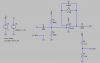
The circuit in the first attachment minus the output divider to out_gnd is what I was originally working on. I can't for the life of me remember where I found the schematic. It works but the output is of course centred at +4.5V. I don't know if that's going to kill a soundcard input, but I'm given to understand they want a maximum of 1V peak to peak. Is that true?
So I added the output divider, which at least works in the sim. It costs 2mA but I can live with that.
Anyway, I've since decided to build this one instead, but I would still like to know: is it reasonable to solve the bias problem with the output divider I've added?
Thanks,
Torben
I am building a soundcard input buffer for use with simple PC oscilloscope (<20kHz) software while I save up for a real scope.
The circuit in the first attachment minus the output divider to out_gnd is what I was originally working on. I can't for the life of me remember where I found the schematic. It works but the output is of course centred at +4.5V. I don't know if that's going to kill a soundcard input, but I'm given to understand they want a maximum of 1V peak to peak. Is that true?
So I added the output divider, which at least works in the sim. It costs 2mA but I can live with that.
Anyway, I've since decided to build this one instead, but I would still like to know: is it reasonable to solve the bias problem with the output divider I've added?
Thanks,
Torben