Continue to Site

Welcome to our site!

Electro Tech is an online community (with over 170,000 members) who enjoy talking about and building electronic circuits, projects and gadgets. To participate you need to register. Registration is free. Click here to register now.

  • Welcome to our site! Electro Tech is an online community (with over 170,000 members) who enjoy talking about and building electronic circuits, projects and gadgets. To participate you need to register. Registration is free. Click here to register now.

Sound to light converter circuit explanation

Status
Not open for further replies.

Tan9890

New Member
**broken link removed**

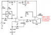
hi.. i've used this circuit in my project.. Its a sound following robot..

however i need a detailed explanation on how this circuit actually functions..

Can anyone help me out? i need to know what each component does and all.. i need it for my report..

Plz help.. Thank you..
 
hi,
If this a homework question it should be in the Homework Forum.:)

You should post what you think is the explanation of the circuit and we will advise you as required.

Where did you get the circuit from.?
The output stage as drawn, will only allow a very small value of current thru the LED's so I dont think you will see them light up.
 
Last edited:
10k for the brightness resistor is much too high.

R7 isn't needed.

I hope the op-amp can withstand negative voltages on its input, check yourself, I haven't looked at the data sheet for the LM358.

The input impedance of U2A is too high.
 
I hope the op-amp can withstand negative voltages on its input, check yourself, I haven't looked at the data sheet for the LM358.

The input impedance of U2A is too high.

The LM358 does not handle large -ve input swings very well, a signal clamp diode, to 0V, on its input improves the performance of the circuit.

Why do you figure the 1st input impedance is too high.??
 
Last edited:
I got it backwards, I meant the impedance is too low, 2k2 will load down the mic circuit too much.
 
hello n thank you....

The circuit works perfectly. I've tested it on the bread-board. Actually i'm cutting off the LED part and giving the collector's output to my micro-controller..

I got this circuit from instructables.com. the brightness of the LED increases with sharper sounds..
And i've increased the 'brightness' resistance to 10K because i need to feed the output to the controller...

Now, as per the hardware, i get around 0.1V for no sound and about 1.5V for maximum sounds.

I dont understand the functioning of the circuit though... the first opamp is in inverting mode, so the output should be -ve, right? however the collector output is +ve voltage....


In short.. th circuit functions almost perfectly, giving 0-1.5V.... but as per theoretical analysis of the circuit...the output should be different...

According to you, how is the circuit functioning now?


Thank you..
hi,
These are images of simulations using the circuit you posted, I would not call it working perfectly, there is less than 1mA in the LED's.
One image is for 1kHz and the other 5kHz.

What do you plan to do with signal into the PIC.?
 

Attachments

  • 1k.gif
    1k.gif
    37.8 KB · Views: 382
  • 5k.gif
    5k.gif
    36.9 KB · Views: 334
Instructables are designed by people who know nothing about electronics.

The opamps are backwards:
1) The preamp opamp should be non-inverting so it does not load down the signal from the mic.
2) The LED driver opamp should be inverting so its input never goes negative.

Other problems:
3) The battery needs a supply bypass capacitor.
4) R1 should be fed from an RC filter.
5) A capacitor to ground should be at the junction of R2 and R4.
 
Thank you, ericgibbs for all the effort u've taken.. I would like to know the software u've used for the simulation.. i'll try it out too.. it seems pretty useful... I did use Proteus ISIS for the simulation... i had got some similar results... low current.. negative voltage...

but when i made this circuit physically.. it does work, and with some minor changes in resistances, i do get a range of 0-1.5V at the collector... that is what i gave as an input to my micro-controller and the robot succesfully works..

But u know what the problem is, i havent actually understood, how the circuit should function in the first place... Why do we need the inverting config anyway?

Can anyone explain to me in short, the full functioning, please? like..
1. the 1st opamp configuration, is it a -ve amplifier with variable gain to achieve sensitivity?
2. the microphone configuration?
3. Is the 2nd opamp a voltage to current converter? If so, can you give me some reference on the actual circuit diagram of a V-I converter?
4. Are R3 and C1 used to filter out the alternating nature of sound to make it DC?
5. What are R6 and 100nF used for?

Also if anyone could suggest some formulae related to the opamp configurations, that would be very useful for understanding....

Sorry for all the trouble, guys.. I appreciate the help very much...
Thank you all...
 
1. the 1st opamp configuration, is it a -ve amplifier with variable gain to achieve sensitivity?
Its an AC coupled inverting amplifier.
2. the microphone configuration?
Its an Electro-met microphone.
3. Is the 2nd opamp a voltage to current converter? If so, can you give me some reference on the actual circuit diagram of a V-I converter?
Its a non inverting amplifier, configured as a current amp using that transistor.

4. Are R3 and C1 used to filter out the alternating nature of sound to make it DC?
R3 and C1 are used as AC coupling

5. What are R6 and 100nF used for?
100nF is AC coupling and the 10K is to reference the 2nd amp input to 0V.

Also if anyone could suggest some formulae related to the opamp configurations, that would be very useful for understanding....

Sorry for all the trouble, guys.. I appreciate the help very much...
Thank you all...

hi,
I am using LTspice, free, join the Yahoo LTSUser group.
 
Last edited:
R3 and C1 are used as AC coupling... that means we're blocking out the DC components... but the output at the collector should be DC, right?

Please sir, if its not too much to ask, can you explain the full operation of the circuit... I'm really confused about the working...
 
R3 and C1 are used as AC coupling... that means we're blocking out the DC components... but the output at the collector should be DC, right?

Please sir, if its not too much to ask, can you explain the full operation of the circuit... I'm really confused about the working...

The 2nd amp should only respond to the positive going half cycles of the sine wave.
So the as its an non inverting amp, these half cycles light the LED's, it not really DC but just the positive going half cycles

Compare it to a simple half wave rectifier.OK.?
 
ok.... now i get it.....
I'll summarize the working, correct me where i'm going wrong,ok...

The audio signal from the mic, an AC signal gets AC coupled through C1,R3.. It is given to the inverting amplifier...

One doubt: the voltage divider using R2,R4 given to the + terminal of the 1st opamp, acts as a reference, right?
Also, if the configuration of the 1st opamp is changed to non-inverting, it wouldn't make any differcnce, right? or it there any reason for it?

Continuing, the amplified signal from the opamp gets inverted and is AC coupled to the 2nd opamp.

Another doubt: you said, "10K is to reference the 2nd amp input to 0V." but it is given to the +ve terminal itself, so does the -ve terminal has its potential as 0?

Continuing..... the 2nd opamp responds to +ve half cycles.. producing positive voltage and the necessary current for the transistor.....

Is the circuit operation correct?
 
ok.... now i get it.....
I'll summarize the working, correct me where i'm going wrong,ok...

The audio signal from the mic, an AC signal gets AC coupled through C1,R3.. It is given to the inverting amplifier...
Correct

One doubt: the voltage divider using R2,R4 given to the + terminal of the 1st opamp, acts as a reference, right?
Its sets the amp operating point voltage at half the supply voltage.
This is needed as its a AC coupled amp
.

Also, if the configuration of the 1st opamp is changed to non-inverting, it wouldn't make any differcnce, right? or it there any reason for it?
It should be a non inverting amp anyway.!
The circuit will need modification

Continuing, the amplified signal from the opamp gets inverted and is AC coupled to the 2nd opamp.

Another doubt: you said, "10K is to reference the 2nd amp input to 0V." but it is given to the +ve terminal itself, so does the -ve terminal has its potential as 0?
The -V of the battery is 0V.

Continuing..... the 2nd opamp responds to +ve half cycles.. producing positive voltage and the necessary current for the transistor.....
Correct

Is the circuit operation correct?

You are making progress.:)
 
Also, if the configuration of the 1st opamp is changed to non-inverting, it wouldn't make any differcnce, right? or it there any reason for it?
The electret mic and the 10k resistor that powers it have a source impedance of about 2.5k ohms. the inverting amplifier has a fairly low input resistance of 2.2k ohms (R3) so the 2.5k source has a load of 2.2k which drops its level to less than half.
If the opamp is made as a non-inverting amplifier then its input resistance could easily be 25k ohms or more so that the mic signal is not loaded down and is not reduced.

Another doubt: you said, "10K is to reference the 2nd amp input to 0V." but it is given to the +ve terminal itself, so does the -ve terminal has its potential as 0?
The (-) input of the second opamp connects to the emitter of the transistor as negative feedback.

Are you going to use the transistor or are you going to remove the transistor take the signal and feedback directly from the output of the opamp?
 
Wow!!!! Thank you so much, sir.... You've been of great help...
I had absolutely no idea that the circuit was functioning this way....
It was reeeally interesting...:)
 
Audioguru, I'm using the transistor in the circuit.. can the opamp output be used directly?

And as for the non-inverting mode... u're saying that, if its in non-inv mode, the audio signal will be more noise-free?
So, the output of the whole circuit will be more accurate.... Is that right?
 
You are using two LM358 dual opamps. One LM358 has two opamps inside so only one is needed for this circuit.
The LM358 is very old and was designed for low supply current so it is very noisy (hiss). Also its high frequency response runs into trouble above only 2kHz.There are many much better low noise wide bandwidth audio opamps available.

I corrected your circuit:
I made the first opamp non-inverting with a fairly high input resistance and added one resistor.
I made the second opamp inverting.
I added important filter capacitors and one resistor.
 

Attachments

  • rectified mic signal to microcontroller.PNG
    rectified mic signal to microcontroller.PNG
    67.8 KB · Views: 360
Status
Not open for further replies.

Latest threads

New Articles From Microcontroller Tips

Back
Top