Continue to Site

Welcome to our site!

Electro Tech is an online community (with over 170,000 members) who enjoy talking about and building electronic circuits, projects and gadgets. To participate you need to register. Registration is free. Click here to register now.

  • Welcome to our site! Electro Tech is an online community (with over 170,000 members) who enjoy talking about and building electronic circuits, projects and gadgets. To participate you need to register. Registration is free. Click here to register now.

Sony SDM-HS74 LCD

Status
Not open for further replies.

timarlop

New Member
Anyone have experience or help troubleshooting this 6 years old -Freecycled- 17" Sony SDM-HS74 LCD ?

At first, when powered on, the symptons were: green power led on, raster with osd but only for 5 sec. or so, then shut off and led turns amber.

Now, as you can see here, when powered on, this info
**broken link removed**
is displayed and the green power led stays continuous on .

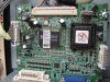
The board is LG 6871TPT285A model PWI7LS285A rev.A

The caps are:

Rubycon long life high ripple YXG

c202 470uF 25V
c203 470uF 25V
c205 1000uF 16V
c315 470uF 25V
c333 470uF 25V

sorry, don't have a esr meter

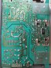
tested power/inverter board conector pins with a dt9205b multimeter:
13.78V at +13V
4.95V at +5V

could it be the microcontroller board ?
 

Attachments

  • P9250005_A.JPG
    P9250005_A.JPG
    273.2 KB · Views: 1,232
  • P9250011_B.JPG
    P9250011_B.JPG
    330.1 KB · Views: 737
  • P9250026_D.JPG
    P9250026_D.JPG
    314.7 KB · Views: 650
you have to replace some caps: 1000µF (2 or 4 can't remember) i have fixed one, this is now my main screen.
 
Welcome to the forum and thanks for the reply!


Haven't been working on it, but I didn't give up yet!

...replace some caps: 1000µF (2 or 4 can't remember)...

Do you remember the brand of caps in that POWER/INVERTER board?


How did you removed your BACK COVER ASSEMBLY ? (my model is black part: 3809TKL085C)

I broke a clip at the top middle of my cover to completely remove it.. LOL


In the smaller mainboard the MST9131B LCD Controller (U201) POWER PINs: VDDP(3.3V)and VDDC(2.5V) are both low (1V).

Noticed small solder balls in the smaller mainboard left side (next to POWER/INVERTER board heat sinks), could also have dry solder joints at 3.3V and 2.5V regulators, I need to check them.

The electrolytic caps in the smaller mainboard are: RJ4 ELNA 16V 100UF.
 
as far as i can see on my screen is everything with screws.. Just test with other condensators it costs not a lot, max 5eur. for me it was the solution! i had sometimes image for over 2h, but also 2s and it powers down amber color. First you can try warm up the condensators if you're screen is working then you have to replace the condensator. when you set the contrast very low (if possible) then you will have an image for an longer time-period. you can also touch all the solders with iron of witch you think they are bad.. after warming up the condensators don't wait to long before powering up..

good luck!
 
Status
Not open for further replies.

Latest threads

New Articles From Microcontroller Tips

Back
Top