Continue to Site

Welcome to our site!

Electro Tech is an online community (with over 170,000 members) who enjoy talking about and building electronic circuits, projects and gadgets. To participate you need to register. Registration is free. Click here to register now.

  • Welcome to our site! Electro Tech is an online community (with over 170,000 members) who enjoy talking about and building electronic circuits, projects and gadgets. To participate you need to register. Registration is free. Click here to register now.

[SOLVED] Need help diagnosing or replacing a 5v transformer?

Status
Not open for further replies.

gkmaia

Member
Can anyone help me diagnose this transformer or suggest a replacement?

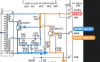
Primary coil takes 5v and the feedback coil takes another 5v. I cannot get any output voltage so I assume it is faulty.

But it outputs to a 3v power regulator and a 1.5v power regulator so I suspect at the same 5v range.

As you can see by the photos. I get no output no matter what.

It has printed on it 3305 n181 and part number is S1673305 and unfortunately I cannot source a datasheet or the part.

IMG_2713.jpeg
IMG_6771.jpg
IMG_9851.jpg
 
I can not see what you are doing.
I see a meter set to AC volts looking at one winding.
Is there a Varta 1.5 volt battery across the primary of the transformer? )[picture 2)
Are you putting 05.00 volts at 0.888 amps on the transformer? (last picture)
 
I can not see what you are doing.
I see a meter set to AC volts looking at one winding.
Is there a Varta 1.5 volt battery across the primary of the transformer? )[picture 2)
Are you putting 05.00 volts at 0.888 amps on the transformer? (last picture)

Photo with battery show testing with a battery. No DC outoput.
Photo with power supply shows testing with power supply. No DC output.
Photo closeup so you can see the transformer closer. Numbers, coils, etc...

Yes, if I set the power supply voltage to 5v the power supply sets 0.8A automatically. It is the amount of current the transformer is asking in order to push 5v.
 
A transformer can not work with DC. Transformers work with AC only.

Where did you get the transformer?
 
T1 here on the photo. DMMV takes 5v. DMMP on high 5v disables the circuit DMMP on low enables Q9 and takes 5v DC to the transformer. That should output something in similar range.

Maybe I should call it a DC/DC converter instead of transformer?

Screen Shot 2019-01-05 at 2.12.11 PM.png
 
Q9 is an oscillator.
T1 pin 2 Voltage = DMMV (maybe 5V)
T1 pin 4 Voltage = AC voltage, when Q9 is on the voltage is about 0V, When Q9 is off the voltage is about twice DMM.
T1 Pin 9 Voltage = AC voltage, About +/- 8V.
Voltage on left side of D6 = DC at about 7.5V.
1546652702842.png
 
When T1 was on the circuit. I was getting:
- 0v on the left side of D6
- DMMV +5v (as it comes from the main board)
- DMMP low = 0v high = +5v
- IC4 (REG LINEAR 3V 250MA SOT89-3) output was 0v
- IC5 (REG LINEAR 1.5V 200MA SOT89-3) output was 0v
- Q9 & Q10 have been tested and both read 0.6v on the right direction

What you suggest? Is there a way to test T1 off circuit?
 
Testing T1: simple
Measure resistance from 1-5, 2-4, 7-9. You should get something low like 1 ohm. All you are testing is if there is wire.
"Open test" If you want you can measure 1-2, 1-7, 2-7 They should measure "open".

A better test is to measure inductance but most people don't have a meter for that. and we don't know what a good reading is.

If you have a signal generator and a scope you can put a signal in on pins 2-4 and see if a signal appears on 1-5 and 7-9. (1 volt at 50khz)
 
That is the DMM board of my leader scope. That will make hard to test it on a scope. Best I have is my multimeter.

input 1-5 gives 3ohms
input 2-4 gives 5ohms
output 6-8 gives 10ohms
There is no continuity between any of the 3 coils

Would you discard the dc/dc converter and look somewhere else for the fault?
 
Probably the transformer is good.
If "DMMP" is high (above 1.5V) then Q10 is on. If Q10 is on then Q9 is forced off. This will stop the oscillation and stop any power from getting to D6 and IC4 and IC5. Please look at DMMP (16) and see if it is near zero or above 1.5V.
1546659269238.png
 
Basically what you are saying is represented by the image bellow right?

When I tested it I got the following which seems right. DMM function of the scope is enabled the DMMP goes low. DMM function is disabled the DMMP goes high.

I will need to wait a bit to test the system running again as I am waiting a few parts for the mother board. Best I can do now while I wait is to test individual components off board.
 

Attachments

  • Screen Shot 2019-01-05 at 7.06.30 PM.png
    Screen Shot 2019-01-05 at 7.06.30 PM.png
    780 KB · Views: 107
As you've been trying to test a high frequency switch-mode transformer using a DC input it's pretty obvious you have little or no experience, or electronics knowledge.

The circuit is a DC/DC converter, to provide a 7.5V supply from a 5V input, it's VERY unlikely that the transformer would be faulty - unless you've damaged it by feeding it with DC.
 
it's pretty obvious you have little or no experience, or electronics knowledge.
Nigel;
Why belittle people with less experience than you.
That's what they do on the other forum and that's why I moved over here.
I'm guessing most members here don't have your experience or electronics knowledge, there's no need to point it out.
Thanks for the beneficial help you do provide.
 
I come to Electro-Tech to discuss electronics with Nigel and my other peers. I left other sites that have many school kids who know nothing about electronics and want people to teach them.
 
I do not have experience and trying to learn from who really knows. People like ronsimpson.

A comment like Nigels and Audioguru are really what makes you want to give up on electronics. And from all the forums I am on, this is the only one where you get people being agressive with beginners. That is on my other posts as well.

So let me ask you a question and for sure be blunt honest.

Are beginners not welcome here?

Let me know. I will cancel my subscription, not hard feelings at all.
 
Other electronics forums have a "Beginners" section where some teachers answer questions correctly or wrongly. I have been a teacher a few times.
Most of us here went to school to learn electronics from real teachers and from good books. I taught my teachers a few tricks I found about electronics.

Gkmaia, it looks like you are trying to repair a defective circuit you have, and you are a beginner in electronics, so maybe your post should be in the Repairing Electronics or Homework section of this website.
 
I come to Electro-Tech to discuss electronics with Nigel and my other peers. I left other sites that have many school kids who know nothing about electronics and want people to teach them.

Your point is well taken. But "certain people" do it chronically and rudely when there is no cause -- even when the person asking the question is making an honest effort, rather than simply soliciting ephemeral information.
That certain grammar and punctuation-challenged person is often incorrect, and, astonishingly, usually arrogant about it.

Other people, who more often than not, ignore or are unappreciative of detailed answers and suggestions -- and others who are completely full of BS, and others who suggest illegal or dangerous activity -- are tolerated and even coddled with nary a peep from moderators or regulars. But gkmaia, who has obviously made an investment in money and time and effort, is treated like an idiot (BY A SUPER MODERATOR, no less!!) for wanting to learn! Shameful!

This comment may get me banned, but it's something I've wanted to say for years, and I'm probably not alone in my opinion.
 
At the photo of thread #11 the blue line shows the oscillator for the DC/DC Converter.
It's hard to find problems here without an oscilloscope.
Obvious it doesn't oscillate, rather DMMP = 0V.
The parts round diode D7 seems to be a load regulation.
When no oscilloscope is availible first thing i would do is check the components ( Resistors, Diodes, Transistors ) of the oscillator part.
Additional D6 and search for shortings to GND behind D6.
All this can be done with an resistor meter an and diode tester ( diode test of multimeter ).
How old is this thing?
The electrolytic capacitators are often the problem in older switching power supplies.
But to test them, You may have an capacitance meter.
C24, C26, C27 could be faulty.
 
One more thing: Are you able to disconnect the load (at the outputs of IC4 and IC5) before testing the circuit? A short-circuit on the output might stop the circuit from oscillating.

Come to that, you should check from the junction of D6 and C27 to ground, to make sure there is not a short. That would mean a short in either D6, C27 or IC4, IC5, which would stop the circuit from working.

Please be very careful when working on CRT scopes, especially around the tube and the EHT lead that connects to its body - the tube itself acts as a capacitor and can store a dangerous charge for weeks.

Regarding terminology, the part that you have removed is a transformer - exactly the same as a transformer that works directly on 50/60Hz AC from a wall outlet, but smaller becuse it is designed to operate at higher frequencies. The entire circuit belongs to a class of circuits called "DC to DC converters" - the circuit takes DC, turns it into AC (because, as you've found, the transformer won't do anything with DC) and then turns the AC out of the transformer back into DC.

Please don't be offended by Nigel... he can be a bit terse, but he's lovely really ;)
 
Status
Not open for further replies.

Latest threads

New Articles From Microcontroller Tips

Back
Top