Continue to Site

Welcome to our site!

Electro Tech is an online community (with over 170,000 members) who enjoy talking about and building electronic circuits, projects and gadgets. To participate you need to register. Registration is free. Click here to register now.

  • Welcome to our site! Electro Tech is an online community (with over 170,000 members) who enjoy talking about and building electronic circuits, projects and gadgets. To participate you need to register. Registration is free. Click here to register now.

Solid State Toggle Switch

Status
Not open for further replies.

Servo Wizard

New Member
Hello,

It has been quite awhile since I have visited this forum. I have a situation where I need to toggle the current on a line by using the signals from the security module on my Harley-Davidson motorcycle. My security module is the early design that requires a push button FOB. My objective is to create a key less ignition switch. I have accomplish that but, there is a problem. What I did not count on was Delphi leaving the system relay unprotected when the security is armed. If someone was to toggle the run/stop switch to run then it activates the system relay which in turn starts the fuel pump and lights the instrument panel as if the bike is ready to run but, it won't due to the security disabling the ignition through the ECM. Delphi provided no usable output from the security module that could be used to control a relay. All that I have is two BEEPS when I arm the security and a single BEEP when I disarm the security.

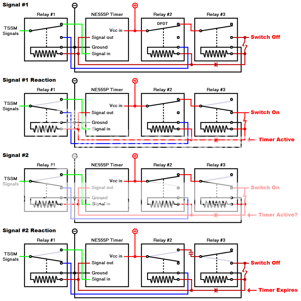
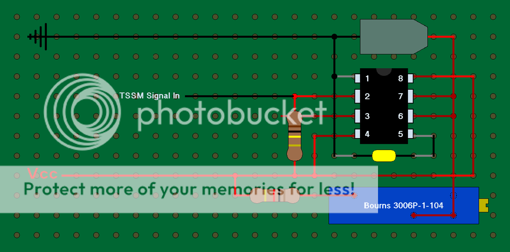
When the security is armed then I need to break the connection to the system relay. I know that the current that creates the tones can be used to toggle the connection but, I don't know how to get there? Do you have any suggestions?

Thanks,
Ron
 
Without seeing a schematic of your system we'd need a crystal ball to be able to offer suggestions :(.
 
Sounds like you need a circuit that breaks the relay connection when it receives two pulses and makes the connection when it receives one pulse.
What is the approximate period of the two beeps?
Can you readily access the signal that generates the beeps?
 
crutschow,

Thank you for sharing your crystal ball with me. ;) Yes your understanding is correct. I have easy access to that signal. I just recently added a PIEZO siren to the motorcycle and that is where the beeps are being generated. I have not timed the beeps but, I'm going to say a ½ to 1 second. I continue to get this image of three timer relays but, so far they are all laying on the bench in their package. I actually have a timer relay floating around in the US Postal Service. It was to be used to lengthen the notification signal from the security module. As is it sounds like a 50s VW horn. I want one complete shrill chirp so everyone will know that I just armed the security module. I would prefer to stay away from an electromagnetic relay if possible.

I have successfully created a key less ignition and only I can start the engine. The problem is that Delphi did not protect the system relay. If someone was to toggle the run/stop switch to run while the security system is armed then it will power up the fuel pump and all of the instrument panel lights come on along with all of the turn signals flashing. If I was away from the motorcycle for a few hours then I might return to find the battery drained.

Arm the security system: BEEP, BEEP. Disarm the security system: BEEP. Those tones are generated with 12 Volts. On the BEEP, BEEP I need to disable the circuit to the system relay and on the BEEP I need to enable the circuit to the system relay.

Ron
 
A microcontroller would be good solution for that.

Alternatively, if you want to use logic gates, you could probably do it quite well with a couple of 4093 ics
( https://www.ti.com/lit/ds/symlink/cd4093bc.pdf )

You would start with making a positive edge triggered one-shot timer, and a negative edge triggered one-shot timer. You would also need a pulse extender circuit, to produce a signal that is ON if a BEEP finished in the last second.

When a BEEP starts, that is detected by the positive edge triggered one shot. If the pulse extender signal is on, at the same time as the BEEP starts, that means that the BEEP is a second one, so the output of the positive edge triggered on-shot, and the output of the pulse extender should be connected to the two inputs of an AND gate. That will operate at the start of the second BEEP.

That signal needs to be extended as well, and combined in a second AND gate with the signal from the negative edge triggered one shot, so that when the second BEEP ends, the circuit disarms.

The time flow would be:-
First BEEP starts.
Positive edge triggered one-shot operates, but it only goes to the AND gate, where the other input is low, so nothing happens.
First BEEP ends.
Negative edge triggered one-shot operates, its output pulse is extended
There has not been a previous pulse, so the system arms.
Second BEEP starts.
Positive edge triggered one-shot operates, and pulse from negative edge triggered one-shot has been extended past this point.
AND gate operates.
Output of AND gate is also extended by second pulse extender.
Second BEEP ends.
Negative edge triggered one-shot operates, second AND gate turns on, disarming the system.
 
Below is the LTspice simulation of a circuit that should do what you want using a one-shot and one flip-flop.
The relay is denergized after receiving 2 beep pulses within the one-shot period, and is allowed to be energized from the Run/Stop switch after a 1 beep pulse.
On the first pulse, the one-shot output goes high, setting the FF D input high. If the one-shot is still high when the 2nd pulse arrives then it triggers the FF Q output to the high state, turning off the P-MOSFET (Vgs = 0V).
After the one-shot times out, the FF D input goes low. The next pulse then triggers the FF Q output low, turning on the P-MOSFET (Vgs = -12V) .
The transistor driving the relay can be just about any P-MOSFET with a 40V or higher rating.
Note that the power and ground pins for the ICs are not shown and must be connected.
The power draw of the circuit is negligible so it can be left powered all the time.

Connect all unused IC inputs (not outputs) to ground.
Not shown is a 100μF filter capacitor you should add from the +12V to ground.

Edit: I just noticed that capacitor C1 must be non-polarized so it needs to be two back-to-back 20μF electrolytic capacitors instead of one 10μF.

Pulse descriminator.gif
 

Attachments

  • 4047 1 pulse 2 pulse descriminator.asc
    2.6 KB · Views: 200
Last edited:
Gentleman,

EDIT: Signal #2 is actually what releases relay #2. Signal #1 just sets relay #3 up so if signal #2 occurs prior to to the timer expiring then it initializes the circuit. This has become rocket science to me and I'm the damn fool that designed the circuit.

I thank all of you for your input. I am a machinist by trade and while I have always had a strange attraction to electricity and electronics I have never taken the time to become educated in the field. I received my formal education at the age of 5 when I removed the light bulb from the night light next to my bed, inserted my finger and then switched it on. That might have something to do with why I'm not so bright today.

What might seem to be straight forward and simple to you is rocket science to me. Logic has always been my strong suit but, you cannot bounce a golf ball in mud. Shown below is a schematic that uses components that I frequently use with the exception of one of the relays having a timer. The toggle is a ground for the relay that replaces the manual ignition switch on my motorcycle.

I would appreciate it if you would DEBUG my schematic. I have illustrated all three of the circuit states, Beep #1, Beep #2 and Timer Expired and numbered the sequence of events as I perceive them.

Thanks,

Ron

Relay%20Logic%20Schematic_zpsikebw4s8.png
 
Last edited:
I'll try simulating your relay circuit but I won't be able to do that until Thursday.
 
I'll try simulating your relay circuit but I won't be able to do that until Thursday.

It dawned on me this morning that I skipped a few circuits on the Timer Relay. Duh! The timer relay has Power in, NO, NC, Ground and a 12V+ signal. The logic prior to and after the timer relay is rock solid and that is what I need to accomplish my task. I know how to integrate the timer relay. I'm sure there is a more sophisticated circuit but, I can make this circuit work.

Thanks
Ron
 
I'll try simulating your relay circuit but I won't be able to do that until Thursday.

crutschow,

Here is a fully baked schematic of my relay logic module. If you have the time then I would appreciate a professional evaluation. I'm a machinist so my symbols will most likely not be found at NIST but, I believe that you will comprehend. The dark red circuits indicate 0V. This design does not leave any of the logic relay coils energized. I plan to use Omron G5V-1-12DC logic relays or NTE R56S-5D.5-12D reed logic relays, however, I'm open to suggestions. Relay #3 will be an automotive relay that is designed to withstand prolonged activation with 15A load.

I know that there must be a way to eliminate the third relay but, I lack the creative knowledge to figure out how to accomplish that. I need to ground relay #2 to common, latch it to Vcc such as I show on relay #3 and then break the ground with the blue circuit that carries the 2nd of the pair of low signal from the TSSM should it ccur while the timer output is high.

To avoid a possible subject matter conflict the last two characters in TSSM stand for Security Module. The TSSM emits two low signals. (1). a single pulse. (2). a pair of pulses with an interval of .1 second. The timer will expire shortly after the time interval between the pair of low pulse signals. I measured the time interval between the pair of low pulse signals at .1 second but, I have not tested for the minimum time that a new signal can be generated, however I don't see anyway that it can occur in less than a ½ second so I will most likely configure the timer for .5 second.

In the illustration below I have shown the relays in their state prior to receiving the signal and their state after receiving the signal. The following is an explanation for how the module is supposed to function.

TSSM Signal #1

Timer is started which sends power to relay #1 causing it to switch so that the second TSSM signal does not restart the timer. Relay #1 remains closed until the timer expires so that it can redirect the second TSSM signal. The timer also supplies power to relay #2 so that it will be ready to close if the TSSM emits a second signal while the timer output is still high. The diode prevents current feed back to the timer.

TSSM Signal #2

If the second signal occurs before the timer has expired then it will ground relay #2 causing it to close which will switch off the power to relay #3 causing it to unlatch and open. That switches the ignition off. The timer will have expired so there will be no current at relay #3 coil.

If you are confident that the pulse discriminator schematic will work then I will revisit that plan.

Ron

Relay%20Logic%20Schematic_zpsikebw4s8.png
 
Last edited:
Your 555 timer diagram is incomplete so am not sure if that works. :confused:
Are you aware that the 555 is triggered by a signal going to ground, not a positive pulse? Your circuit seems to assume a positive trigger (the TSSM signal).
 
Your 555 timer diagram is incomplete so am not sure if that works. :confused:
Are you aware that the 555 is triggered by a signal going to ground, not a positive pulse? Your circuit seems to assume a positive trigger (the TSSM signal).

crutschow,

Actually my application signals are a momentary short to ground. On the second of the mentioned pair of signals (blue circuit) it grounds the coil on relay #2 causing it to close and that breaks the Vcc connection to relay#3. As for the timer I do have a full timer circuit but, I included only what was pertinent to the relay switching logic.

Below is my timer circuit. Half red and half black circuits are on the underside of the board while full red and black are on the top side. In some cases the circuit weaves through the board in order to secure the circuit to the board. The VR is 100k and the tantalum capacitor is 10uF which will yeild .11 to 1.1 second time interval based on 10k to 100k. As I stated I will most likely fix the resistance at 50k for an approximate .5 second timer output at pin #3

Ron

555%20EXPORT_zpsuulhdedc.png
 
Last edited:
Your circuit shows the TSSM signal controlling a relay directly. Is the TSSM signal able to handle the relay coil current?

How can Relay #3 turn on with the diode in series?

What keeps the Relay #3 on when you get only one TSSM pulse (disarmed) and the timer expires?

I'm reasonably confident that the pulse discriminator circuit I showed will work, but since it's only been simulated and not built, there's no guarantees. ;)
 
Last edited:
Someone could hack that with two hand claps, then if you had a bandpass filter, it could be hacked with a recording on a cell phone. Then beyond this, hack the system wiring even if the relay was secured.

Clearly a 2nd FOB is best for the system Relay to prevent battery loss. Cheap wireless rolling code encryption keyfob with reed relay out to activate system relay. Cheap and dirty.... But not single switch.

The features , cost, complexity with security are all tradeoffs. An upgrade is a new rollingcode keyfob that activates the system and Delphi Tx at the same time both embedded inside the delphi unit with booby trap.

Gee my old pay tv security designs are coming back to me. You could also use biometric finger with serial rolling code to Delphi and system relay reader , to arm all. But Rx must be embedded with I2C interface.

Tony,

I'm comfortable with the Delphi TSSM security system. It is not a recognition type system like the newer models nor am I interested in that type of security.

I already have a key-less ignition switch that uses the push button FOB to switch the ignition on and off. Unlike the commercially available system call Digital Guard Dawg my bike cannot be started once the security system has be armed. With Digital Guard Dawg anyone with advanced H-D knowledge can access the ignition switch pig tail, insert a paper clip, start the engine and ride off. Now if they use the TSSM in conjunction with the Digital Guard Dawg then they are truly secured. Why pay $425.00 for a supposedly secure system that requires the TSSM in order to provide the security they boast about?

My current system has short comings but, security is not a problem. If the security is armed then it switches the ignition circuit off. When the security is disarmed then it switches the ignition on. The problem is that when armed if some one toggles the Run/Stop switch to Run then it activates the system relay and the fuel pump spins up and lights flash. Flashing lights might run the battery down depending on the length of time that the bike was unattended. The fuel pump running constant against the bypass will burn out the pump motor. Delphi chose not to secure that circuit. The starter relay ground is made by the TSSM. I thought that I could eliminate the problem by tying system relay ground to the starter relay ground. The SOB totally ignored what I did because nothing changed. The system relay will not work with out a ground so I thought about running it's ground circuit through a relay controlled by the starter relay ground that the TSSM furnishes only when the it is unarmed.

I may rapidly return to that thought once crutschow gets through explaining why my plan won't work. That is exactly why I asked for his evaluation.

Ron
 
Last edited:
Your circuit shows the TSSM signal controlling a relay directly. Is the TSSM signal able to handle the relay coil current?

How can Relay #3 turn on with the diode in series?

What keeps the Relay #3 on when you get only one TSSM pulse (disarmed) and the timer expires?

I'm reasonably confident that the pulse discriminator circuit I showed will work, but since it's only been simulated and not built, there's no guarantees. ;)

crutschow,

First let me say that this has nothing to do with security. I'm already using the TSSM push button FOB for a key-less ignition but, it is has a quirk, however, it is secure. While security is armed if some one toggles the Run/Stop switch to Run then it activates the system relay. That spins the fuel pump up and causes the lights to flash. Flashing lights might run the battery down but, the fuel pump running constant against the bypass will burn the motor out. I have a fix for my current system but I wanted to try an approach that does not require re-wiring the motorcycle. Another relay in my current system would solve the problem and I might have to settle for that but, it will be a last resort. I'm shooting for an extremely small module that when potted will plug directly into the ignition switch pig tail and the TSSM signal lead connector. My current system required some extensive circuit modifications but, I'm religious when it comes to hacking up circuits. I purchased the Deutsch crimping tool and a supply of pins and sockets so that I can reverse all that I have done.

Your points:

I have not load tested the TSSM signal with anything other than an 1157 bulb and a piezo siren that I installed. I'm not overly concerned about the TSSM signal strength as long as it is sufficient to trigger the timer. If necessary I may have to boost the signal.

Regarding the diode. It is reversed. (Damn amateurs) I did not want current from relay #3 returning to the timer. I question if it would harm the timer. I had to use the timer output to close relay #3 so that it would latch on to Vcc.

Regarding Relay #3. As long as relay#2 is open then it supplies Vcc to the COM on relay #3. When the timer fires then the timer current closes relay #3 and it latches to Vcc. If relay#2 momentarily closes then it switches off the power to relay #3 off and that causes relay#3 to unlatch and open.

I use to build multiple stage tooling that required timing to assure that it did not crash. I assume that with electronics every thing happens at once so timing is not an issue. I'm sure that I'm probably WRONG. The only problem that I see is relay#2 returning to open state when the timer expires and switching power back to relay #3 leaving it latched on to Vcc when not wanted. If that is a problem then could I use a capacitor to provide latency so that relay#2 stays closed for a period after the timer expired?

Thank you for taking time to look at my schematic. I know from my own experience that it is very difficult to get your head wrapped around someone else's logic. I was away from my own logic for a couple of weeks and I had to start from square one and rebuild what I once considered to be sound logic.

Ron
 
keyfob or passive RFID or secret interrupt to run/stop switch may solve your problem. Bikes are not enclosed like cars.

Where I came from, all cars are insured by the cheapest Govt Auto Insurance in the country. All older cars without secure doors and alarms got free Interrupters under the hood.

I once lost the dongle, which at the time, looked like a pendant on my Mother's keychain for her car but is actually a passive RFID. It turned over but no spark. Even the mechanic could not fix it or get spark. Until I found the broken RFID pendant (epoxy lozenge) and he said sorry I cannot fix it and when I put it near the key entry and turned the key it started and I drove away. But I felt guilty driving away, doh!

Tony,

Very interesting but, the topic is an evaluation of my circuit. I'm content with my security system.

Ron
 
Status
Not open for further replies.

Latest threads

New Articles From Microcontroller Tips

Back
Top